
Hi,
I have an Audio Innovations Alto integrated amp that I am trying to fault find.
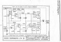
The left channel is good, the right channel not so good - there is audio there (from speaker) but very distorted. I managed to find some schematics and attempted the quiescent current setup. Left channel perfect but on the right I can setup the 50% supply voltage on right hand side of R22 but I get no voltage drop across it (when I should get about 30mV).
I believe all transistors are 'on' that is there is about .6V across all B-E junctions, the zener is ok as are the 3 diodes near it.
Alll caps have been replaced or swapped side to side.
The VR2 pot is good.
I am no electronics guru (just a bit of basic knowledge) - what would be my next logical step in fault finding?
I know the fault is staring me in the face but I can't see it. One channel is good the other not, so short of swapping every component one by one (I have almost done that I think) what would you do?
Thanks in advance
I have an Audio Innovations Alto integrated amp that I am trying to fault find.
The left channel is good, the right channel not so good - there is audio there (from speaker) but very distorted. I managed to find some schematics and attempted the quiescent current setup. Left channel perfect but on the right I can setup the 50% supply voltage on right hand side of R22 but I get no voltage drop across it (when I should get about 30mV).
I believe all transistors are 'on' that is there is about .6V across all B-E junctions, the zener is ok as are the 3 diodes near it.
Alll caps have been replaced or swapped side to side.
The VR2 pot is good.
I am no electronics guru (just a bit of basic knowledge) - what would be my next logical step in fault finding?
I know the fault is staring me in the face but I can't see it. One channel is good the other not, so short of swapping every component one by one (I have almost done that I think) what would you do?
Thanks in advance
Attachments
-
 157 KB Views: 65
 -
 248.2 KB Views: 92

")


