
First off. Hello everyone! I want to start by saying that I appreciate any help I may be about to get. I understand that you folks are all busy and I appreciate taking the time to help me.
I have an old boat that I want to modify the electric start in. I understand the basics of wiring but I'm not very good when it gets at all complicated. With that being said, my wife tells me that everything I do I make 10x more complicated that it needs to be. As usual she is right.
I could just wire in a new ignition switch and connect 6 wires and be done. I don't want to. I want something a little more fun. I know its completely unpractical but I want to at least figure out the solution. Even if I don't do it, I want to understand how to do it.
This is what I'm hoping to do:
The ideal sequence for starting the motor would be:
1. Flip the ignition switch to on or run or whatever. (something like a toggle switch)
2. Flip the choke to on (or hold if its momentary). (Toggle or momentary switch)
3. Push start button. Engine starts(hopefully ) (A push button switch)
4. Flip/release choke switch.
5. Then when I need to turn the engine off I just flip the ignition to the off position.
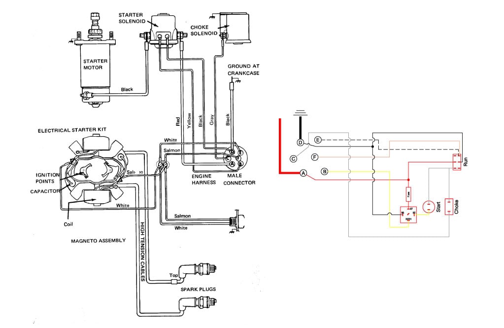
Here is a link to my wiring diagram for my boat.
You'll notice that it uses a 6 pin ignition switch This is what I'd like to replace with a series of toggle switches and buttons. Ignition switch to allow the engine to start (this would also act as a kill switch ideally). A choke switch, and a push button start. You'll also notice a button labeled "Ignition start button" this is mislabeled. You press that button and it actually kills the engine.
Ok, now on to the good stuff. I have come up with a wiring diagram, but I've been told that its wrong. I'll explain the issues the other guy has brought up.
Here is my diagram:
One issue he brought up I struggled with at first is that unlike a car ignition which is a battery ignition, this system is a magneto ignition. This is what he has said about the two:
"Again -- battery ignition requires a CLOSED circuit to engergize the ignitiion. A magneto system requires an OPEN circuit for the engine to run. If you plan to use a toggle switch as a separate On-Off switch it will work but it will work backwards. OFF (open) would be the RUN position. ON (closed) would be the STOP position. To make this a little clearer, a battery ignition (like your car) is like turning on the light in your house. You CLOSE the switch contacts to make the light turn on. With a magneto system it works backwards. You are not energizing a magneto system ignition system but rather allowing it to operate. YOu do that by removing a ground connection that kills the engine to stop it. That ground connection is removed by moving the switch to the OFF (open) position."
He also gave me some good feedback of how things need to work.
"ENGINE START:
1) The IGNITION switch needs to be a set of OPEN contacts for the magneto. This switch is in the kill circuit for a magneto engine. It shorts the ignition to ground. Note that I said "ignition" not the ignition coil.
2) If you use the fancy push button, one terminal of that swtich has +12 volts on it. The other goes to the start relay coil. The other side of the coil goes to ground.
3) When you push the START button, the relay coil is energized which closes the relay contacts. One side of those Normally open contacts has +12 volts on it. The other contact goes to the starter solenoid.
4) The solenoid must be grounded.
5) The POS battery cable goes to one of the large terminals on the solenoid. The other large terminal goes to the starter motor.
6) You should now be able to press the button and the starter will spin.
7) If the engine has a manual choke you need nothing for it. If it has an electric choke you need a switch to actuate the solenoid or primer. Again, +12 volts on one side of the swtich, the other side to the choke solenoid or primer.
8) To kill the engine you simply short the ignition (kill wire) to ground via the ignition switch. You do NOT need a DPDT switch for this. This is a SPST switch. OPEN = RUN, CLOSED = STOP. Don't know what you are attempting to do with a DPDT switch."
Now, I am not seeing where I am going wrong in my diagram. Here are my assumptions on how things work. I'm hoping to clarify that I am right or wrong.
1. With the DPDT (on-on) type switch when one side of the switch is closed the other side is open.
2. Simply put, in order to kill the engine you have to connect one (or both, not sure here) of the white or salmon wires...which are connected to the ignition points, to a ground wire. I'm assuming these wires would be the ignition wires, since they are connected to that part of the system. The switch does this by running a ground into the same side on the contacts as the white and salmon wires, just in the middle position.
Here is how I got to where I am.
1. Flip the switch to the "Run" position, which provides power to the "Start" button. This is done by routing the 12v+ through the switch labeled run in my diagram and then to the start button. This also provides power to the choke switch.
2. Press the choke button. This activates the choke solenoid via a gray wire labeled in the diagram going to "C" This solenoid is grounded up where it is connected to the engine housing.
3. Press the start button. This delivers power to the starter solenoid via the yellow wire routed through "B". Again this is grounded up where it connects to the engine housing. It is also connected to the battery via what look like 6ga or 8ga wires (through the wire harness)
Now the engine is running and its time to kill it to catch a giant fish
1. Flip the switch labeled run in the diagram to the "Kill" position. This connects the white and salmon wires with the ground wire. Which I think, if I understand right, is what needs to happen in order to kill the engine.
Sorry for the long post. I appreciate you reading all this. I really want to understand the problem here and what the correct solution would be. Thanks in advance.
I have an old boat that I want to modify the electric start in. I understand the basics of wiring but I'm not very good when it gets at all complicated. With that being said, my wife tells me that everything I do I make 10x more complicated that it needs to be. As usual she is right.
I could just wire in a new ignition switch and connect 6 wires and be done. I don't want to. I want something a little more fun. I know its completely unpractical but I want to at least figure out the solution. Even if I don't do it, I want to understand how to do it.
This is what I'm hoping to do:
The ideal sequence for starting the motor would be:
1. Flip the ignition switch to on or run or whatever. (something like a toggle switch)
2. Flip the choke to on (or hold if its momentary). (Toggle or momentary switch)
3. Push start button. Engine starts(hopefully ) (A push button switch)
4. Flip/release choke switch.
5. Then when I need to turn the engine off I just flip the ignition to the off position.
Here is a link to my wiring diagram for my boat.
You'll notice that it uses a 6 pin ignition switch This is what I'd like to replace with a series of toggle switches and buttons. Ignition switch to allow the engine to start (this would also act as a kill switch ideally). A choke switch, and a push button start. You'll also notice a button labeled "Ignition start button" this is mislabeled. You press that button and it actually kills the engine.
Ok, now on to the good stuff. I have come up with a wiring diagram, but I've been told that its wrong. I'll explain the issues the other guy has brought up.
Here is my diagram:
One issue he brought up I struggled with at first is that unlike a car ignition which is a battery ignition, this system is a magneto ignition. This is what he has said about the two:
"Again -- battery ignition requires a CLOSED circuit to engergize the ignitiion. A magneto system requires an OPEN circuit for the engine to run. If you plan to use a toggle switch as a separate On-Off switch it will work but it will work backwards. OFF (open) would be the RUN position. ON (closed) would be the STOP position. To make this a little clearer, a battery ignition (like your car) is like turning on the light in your house. You CLOSE the switch contacts to make the light turn on. With a magneto system it works backwards. You are not energizing a magneto system ignition system but rather allowing it to operate. YOu do that by removing a ground connection that kills the engine to stop it. That ground connection is removed by moving the switch to the OFF (open) position."
He also gave me some good feedback of how things need to work.
"ENGINE START:
1) The IGNITION switch needs to be a set of OPEN contacts for the magneto. This switch is in the kill circuit for a magneto engine. It shorts the ignition to ground. Note that I said "ignition" not the ignition coil.
2) If you use the fancy push button, one terminal of that swtich has +12 volts on it. The other goes to the start relay coil. The other side of the coil goes to ground.
3) When you push the START button, the relay coil is energized which closes the relay contacts. One side of those Normally open contacts has +12 volts on it. The other contact goes to the starter solenoid.
4) The solenoid must be grounded.
5) The POS battery cable goes to one of the large terminals on the solenoid. The other large terminal goes to the starter motor.
6) You should now be able to press the button and the starter will spin.
7) If the engine has a manual choke you need nothing for it. If it has an electric choke you need a switch to actuate the solenoid or primer. Again, +12 volts on one side of the swtich, the other side to the choke solenoid or primer.
8) To kill the engine you simply short the ignition (kill wire) to ground via the ignition switch. You do NOT need a DPDT switch for this. This is a SPST switch. OPEN = RUN, CLOSED = STOP. Don't know what you are attempting to do with a DPDT switch."
Now, I am not seeing where I am going wrong in my diagram. Here are my assumptions on how things work. I'm hoping to clarify that I am right or wrong.
1. With the DPDT (on-on) type switch when one side of the switch is closed the other side is open.
2. Simply put, in order to kill the engine you have to connect one (or both, not sure here) of the white or salmon wires...which are connected to the ignition points, to a ground wire. I'm assuming these wires would be the ignition wires, since they are connected to that part of the system. The switch does this by running a ground into the same side on the contacts as the white and salmon wires, just in the middle position.
Here is how I got to where I am.
1. Flip the switch to the "Run" position, which provides power to the "Start" button. This is done by routing the 12v+ through the switch labeled run in my diagram and then to the start button. This also provides power to the choke switch.
2. Press the choke button. This activates the choke solenoid via a gray wire labeled in the diagram going to "C" This solenoid is grounded up where it is connected to the engine housing.
3. Press the start button. This delivers power to the starter solenoid via the yellow wire routed through "B". Again this is grounded up where it connects to the engine housing. It is also connected to the battery via what look like 6ga or 8ga wires (through the wire harness)
Now the engine is running and its time to kill it to catch a giant fish
1. Flip the switch labeled run in the diagram to the "Kill" position. This connects the white and salmon wires with the ground wire. Which I think, if I understand right, is what needs to happen in order to kill the engine.
Sorry for the long post. I appreciate you reading all this. I really want to understand the problem here and what the correct solution would be. Thanks in advance.
 My point is, think a LOT about the human "interface" when you're choosing switches and arranging them. Have you thought about keeping water out of the switches (and blood, beer, fish slime, etc.)? Mine have integral rubber bulbs over the pushbuttons. Things happen. Also consider how toggle switches might be easy to flip inadvertently with fishing tackle, anchor lines, wind-blown clothing, etc.


