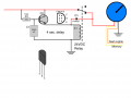
I have this LTSpice simulation. It does what I want it to do (time wise) to wait approximately 4 to 5 seconds before switching the load on. In my sim I'm using 14.4 volts because it's conceivable a car battery will charge to 14.4 volts (and will likely settle down around 13.6 to 13.8 volts). I'm unsure of what the load is but it is small. On the order of less than 2 amps.
What has me confused is why the Vout (test point) is showing about 9.5 volts. The opamp should turn the MOSFET on, right? Should be hard on. NO? I'm confident my circuit can't operate on that low voltage. And when the car battery settles down to around 13.8 volts I'm sure the voltage will only drop even lower. How do I overcome this problem?
[edit] I have a 3405 but Spice has the closest MOSFET as a 1405. But even looking at the spec sheet for 1405, the full on resistance should be only 5.3mΩ
Attachments
-
1.5 KB Views: 25
Last edited: