Limit switch for actuator help

Thread Starter

StealthRT

Joined Mar 20, 2009
303
Hey all i have bought a actuator from firgelli auto and i need to add a limit switch for the down part.


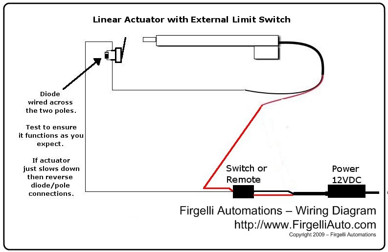
That is a drawing from the company's website about how to hook up the limit switch. Now i have 2 problems with this drawing:

1) It does not tell me what type of switch to get
2) Wont this hinder the up part if the ground is cut off when it hits the lever?

They sell a kit with the limit switch(s) and other things but again they do not tell what type of limit switches they are.

http://www.firgelliauto.com/product_info.php?cPath=70&products_id=111

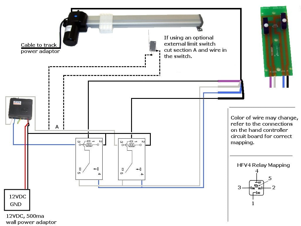
I plan on hooking the up/down to a relay (2 of them) that i control via a PC. They have a diagram for that as well


I emailed them and asked them if this would work with my own setup:
RELAY UP:
> Purple wire > C
> Grey wire > NC
> Blue wire > NO

> RELAY DOWN:
> Black wire > C
> Grey wire > NC
> Blue wire > NO
My relays look like so:


And this is a PDF of the relay:
http://denkovi.com/Documents/23-3.pdf

Any help would be great to (1) See what type of limit switch i need to buy and (2) Make sure my layout for the relay is correct.

Thanks!

David
 

SgtWookie

Joined Jul 17, 2007
22,230
I do not agree with the passing of the actuator current through the limit switch; limit switches as depicted in the 2nd image of your post are not rated for carrying high current.

What the switch should do is cut the power to the relay coil once the limit switch is hit; that way the relay drops out, and it should not affect the operation in the other direction if the relays have been wired properly.

I'm not at home, so I can't post the schematic at the moment; I don't have my stuff with me.
 

colinb

Joined Jun 15, 2011
351
2) Wont this hinder the up part if the ground is cut off when it hits the lever?
If I understand your question correctly, you are asking whether the limit switch will prevent the actuator from operating in the reverse direction (away from the limit switch) once it has hit the limit.

So, you want to control the motor in both directions. I take it this is a regular dc motor and you just reverse polarity of the power to the motor to operate in the other direction. In that case, you need to connect the limit switch in series with the signal controlling the “down” direction only, but leave the limit switch out of the “up” direction circuit.

Here is one way to do it using only relays and a limit switch (which does not carry motor current):


The two inputs are FWD/REV# and ENABLE. The limit switch only prevents the motor from going in the forward direction.
 

Thread Starter

StealthRT

Joined Mar 20, 2009
303
If I understand your question correctly, you are asking whether the limit switch will prevent the actuator from operating in the reverse direction (away from the limit switch) once it has hit the limit.

So, you want to control the motor in both directions. I take it this is a regular dc motor and you just reverse polarity of the power to the motor to operate in the other direction. In that case, you need to connect the limit switch in series with the signal controlling the “down” direction only, but leave the limit switch out of the “up” direction circuit.

Here is one way to do it using only relays and a limit switch (which does not carry motor current):


The two inputs are FWD/REV# and ENABLE. The limit switch only prevents the motor from going in the forward direction.
Thank you for taking the time to draw that up for me :)

However, here are a few things to consider that i may have not been clean on:

1) I only need one limit switch for the down position. It has a built in limit switch for both up and down so it stops where it needs to when going up (all the way). But i do not need it to go all the way down.

2) I will be controlling these via the relays themselves-no switches. But i think you already addressed that.

3) Not sure what the 3rd relay really is for?

4) Are the COM for relay K1 Purple and relay K3 black? Or are both of those just 12v line?

5) Is T1-T2 12v lines?

Thanks!

David
 

colinb

Joined Jun 15, 2011
351
Thank you for taking the time to draw that up for me :)

However, here are a few things to consider that i may have not been clean on:

1) I only need one limit switch for the down position. It has a built in limit switch for both up and down so it stops where it needs to when going up (all the way). But i do not need it to go all the way down.
OK, so you are basically adding an extra down-limit switch. You just ignore the built-in lower limit switch since it won't be involved.

2) I will be controlling these via the relays themselves-no switches. But i think you already addressed that.
The T1 and T2 terminals are the signal inputs to control the relays. Set T1 high to run the motor. T2 indicates which direction to run it. You could control these inputs with switches, or from digital logic, or whatever.

3) Not sure what the 3rd relay really is for?
You need two relays to reverse the motor current. The third relay is there to allow simpler control inputs by providing a direction input and an enable input. You could also design a circuit that would only require the two SPDT relays but then the input signals would be a little less obvious.

4) Are the COM for relay K1 Purple and relay K3 black? Or are both of those just 12v line?
I don't know what color your components use. That's a matter of specific relay models.

5) Is T1-T2 12v lines?
That would depend on your relay coil requirements. The relay will define what its coil voltage is (5 V, 12 V, etc.). It is independent of the motor voltage. For instance, you could use 5 V relays to control 12 V motors. (“5 V relay” is an indication of the voltage supplied to the coil to turn it on, not of the maximum contact voltage.)
 

SgtWookie

Joined Jul 17, 2007
22,230
This is very close to Colinb's suggestion, less one relay and drawn a bit differently. Since it's basically an H-bridge, I drew it in mirror-image form; this can be easier to understand than the standard inputs-on-the-left-outputs-on-the-right method that we all know and love. :)

This is a schematic I made for someone on here a couple years ago:


Yours could be the same thing, just replace S3 or S4 with a piece of wire.

You press S1 or S2 to make the motor run in one direction or another, and the limit switches will disable the relay it's associated with when the limit is struck.

As far as the S3 or S4 switch, you'd need something like this:
http://www.radioshack.com/product/index.jsp?productId=2049719&filterName=Type&filterValue=SPDT
or this:
http://www.radioshack.com/product/index.jsp?productId=2049718&filterName=Type&filterValue=SPDT

The 1st one has a 250v 5A rating, but I don't like to use those little switches for anything other than powering relay coils.

If the relay current will be less than about 80mA, the diodes should be changed to 1N914/1N4148 type switching diodes, as they are much faster than the 1N400x series diodes.

If you really wanted a "run/stop enable" function, just add another switch in series with the ground side of the relays; a 3rd relay isn't necessary.
 

Attachments

colinb

Joined Jun 15, 2011
351
As I predicted, that is more elegant than my design! :) Yes, I was going to also point out that it is really a relay-based H-bridge, and drawing it that way makes it easy to read.
 

Thread Starter

StealthRT

Joined Mar 20, 2009
303
Alright, give me a few minutes to draw up something. I think i have it but i would like to be sure of that before i go hooking it up and all :)

David
 

strantor

Joined Oct 3, 2010
6,781
looks like you're pretty much set on the electrical stuff; just wanted to point out that if you mount your limit switch in the movement path of the actuator like they show in their little pictograph, the intertia of the rod will probably crush the limit switch or shear it off of wherever you mounted it, at which time it will probably make the connection again and your rod will start moving again, crushing whatever else is in its path. Better to mount the limit switch off to the side, where the rod will gently move it to the side, like this:
 

Attachments

colinb

Joined Jun 15, 2011
351
just wanted to point out that if you mount your limit switch in the movement path of the actuator like they show in their little pictograph, the intertia of the rod will probably crush the limit switch or shear it off of wherever you mounted it, at which time it will probably make the connection again and your rod will start moving again, crushing whatever else is in its path.
Good point! But, you just deprived him of that exciting and destructive spectacle! Although I think this actuator may be fairly slow-moving so perhaps it wouldn't be an issue...?
 

Thread Starter

StealthRT

Joined Mar 20, 2009
303


I got a little confused as to how to hook up the limit switch. I can see that there's 3 pins on it (according to the radioshack image) but don't have the pin-out for it so i really don't know whats what. But even knowing that, i'm not sure how to hook that up between the relay and the actuator itself.

Does the limit switch have a current NO port and once it hits the button it shuts it off so no flow is going to the down relay?

David
 

colinb

Joined Jun 15, 2011
351
I got a little confused as to how to hook up the limit switch. I can see that there's 3 pins on it (according to the radioshack image) but don't have the pin-out for it so i really don't know whats what. But even knowing that, i'm not sure how to hook that up between the relay and the actuator itself.

Does the limit switch have a current NO port and once it hits the button it shuts it off so no flow is going to the down relay?
Those three pins on the limit switch are likely a common, normally-open, and normally-closed contact. Check it with a multimeter in resistance mode or continuity mode.

You should consider SgtWookie's schematic. Do you understand it? If you only want one limit switch, just leave the other one out. It looks like you are still putting motor current through the limit switch, which may or may not be allowable depending on your maximum motor current and the switch's maximum current rating.

You CAN'T put the limit switch on the common port of the relay as your last diagram shows. If you are connecting it as an H-bridge (both my schematic and SgtWookie's do this, in fact), then you need one SPDT relay on each side of the motor to allow reversing the current. The limit switch must not prevent current from flowing when you put the motor in reverse!
 

SgtWookie

Joined Jul 17, 2007
22,230
David,
Now you're trying to confuse US! ;)

I don't know what the color scheme for your wires are, but the gray should be ground, blue-gray +12v, black and violet are motor leads. If the red thing is the switch, you should not have it connected to the motor wires; you should have it in the relay coil wiring. However, you don't have the relay coil wiring showing.
 

colinb

Joined Jun 15, 2011
351
P.S. your little clip of the schematic isn't too helpful ... if you could post the full schematic then we could provide more useful feedback. How is the motor connected to the relays and to power?
 

Thread Starter

StealthRT

Joined Mar 20, 2009
303
Ok here are some pictures of the remote i just took:


Now im not sure if you're getting confused as to what i am connecting the relays too but its just being connected to a remote control (with up/down buttons). It (guessing) only passes 12vdc through it and not AC.

As you can see by the colors its:
BLACK = DOWN
WHITE = GROUND
RED = 12v
PURPLE = UP


Maybe i make more since now. :)

Still dont know how to hook it up from the remote to the limit switch then to the down relay.

David
 
Last edited:

colinb

Joined Jun 15, 2011
351
In this diagram, the “DOWN” relay looks like it's not a down-relay but just switches direction. The red box must be your motor, right? It has two inputs, but only one can be connected at a time (“DOWN” relay NC and NO contacts) so I assume the motor has its own ground connection that is not shown on your diagram. The motor must go forward if a positive voltage is put on one of the terminals shown and go in reverse if a positive voltage is put on the other terminal. I don't know how that would be implemented in the motor itself. Anyway, if that's the case, then you need a different design from the H-bridge type design SgtWookie and I have discussed.

Can you define your motor's connections more clearly? Does the remote supply power to the circuit? I don't see where power comes into the diagram. Can you draw a complete diagram showing all power connections and all connections to the motor?
 

SgtWookie

Joined Jul 17, 2007
22,230
OK, I think I see where the confusion is now.

David, you will either have to cut the relay coil trace on your remote control relay board to splice in the limit switch, or you will need to use another SPDT automotive-type relay in order to use the limit switch. If you really don't want to buy another relay, then you can basically use the schematic that Figarelli sent to you, only you will lose some power due to the diode in the one direction, and the limit switch will have it's contacts burned much more quickly than a relays' contacts would burn.
 

Thread Starter

StealthRT

Joined Mar 20, 2009
303
OK, I think I see where the confusion is now.

David, you will either have to cut the relay coil trace on your remote control relay board to splice in the limit switch, or you will need to use another SPDT automotive-type relay in order to use the limit switch. If you really don't want to buy another relay, then you can basically use the schematic that Figarelli sent to you, only you will lose some power due to the diode in the one direction, and the limit switch will have it's contacts burned much more quickly than a relays' contacts would burn.
I've just probed some on the remote control and it seems that RED is ground and WHITE is 24v? The relays are only rated to 12v (or is that all the way up to 24v?). Is this doable?

David
 
Top