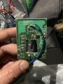
LED's in Momentary Push Button Switch 1NO1NC

Bhunt83

Joined Sep 15, 2019
12
hi

We need to see a schematic of the circuit.
That would eliminate a lot of guess work.
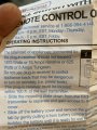
Do you have a part number and mfg for the wall switch so we can maybe find a schematic. If not, the only other thing to do is trace the PCB and make one...

eT
I have an image of the unit attached

the board is an rft1600 transmitter
 

Attachments

Last edited:

eetech00

Joined Jun 8, 2013
3,959
I have an image of the unit attached

the board is an rft1600 transmitter
HI

What we really need to see is the schematic part of the circuit that feeds the two pins that connect to each pushbutton.
You may have to use a couple of small relays, or transistors, to act as a flip flop. Would you be able to handle that?

eT
 

MisterBill2

Joined Jan 23, 2018
18,587
Several posts have asked for a circuit, and I am asking for at least a more detailed description of the functionality of the present circuit. AND, very imortantly, the voltage on the switch. If it is 12 volts or less then a simple addition will be a CD4013 set/reset flip flop driving the LEDs. But if the drive is a higher voltage, or an AC voltage, then it gets a bit more complex. But without providing more information you are getting guesses, some much better than others, but still guesses.
 

Bhunt83

Joined Sep 15, 2019
12
Several posts have asked for a circuit, and I am asking for at least a more detailed description of the functionality of the present circuit. AND, very imortantly, the voltage on the switch. If it is 12 volts or less then a simple addition will be a CD4013 set/reset flip flop driving the LEDs. But if the drive is a higher voltage, or an AC voltage, then it gets a bit more complex. But without providing more information you are getting guesses, some much better than others, but still guesses.
Sorry, I thought I had explained it.

the board is a transmitter for a wireless wall outlet. Runs on 12v. The switches are also 12v. All I did was remove the original non illuminating switches for the illuminated ones I purchased
 

Bhunt83

Joined Sep 15, 2019
12
HI

What we really need to see is the schematic part of the circuit that feeds the two pins that connect to each pushbutton.
You may have to use a couple of small relays, or transistors, to act as a flip flop. Would you be able to handle that?

eT
not without some fairly good simplistic directions, or YouTube videos.

my knowledge is only with switches, leds, and resisters up till now. For reference, attached is the box I build that this project is for.
 

Attachments

eetech00

Joined Jun 8, 2013
3,959
Hi

Here's a circuit that might do the job.
It depends, however, on the signal coming out of the PCB to the pushbuttons. This signal must be referenced from the same DC source polarity in the PCB, otherwise magic smoke will spew:eek::D. You can see in the circuit below that when neither button is pressed, there is a short between Br1 and Br2. As long as these pins are at the same polarity, shouldn't be a problem.

The circuit is basically a BJT flip flop circuit. The OFF (RED) led lights at power up. Pressing the ON button toggles the LED's and supplies an input signal to the PCB. The LEDs shown in the Flip-Flop circuit are optional but could be used to show status wherever the Flip-Flip circuit is located.

eT

upload_2019-10-19_19-32-13.png
 

eetech00

Joined Jun 8, 2013
3,959
Hello

Here is a relay version.
Both relays are off at power on, so one would have to manually set the initial state by pressing one of the buttons. After that, the relays will toggle automatically. D3 and D4 may not be needed (depending on the relay timing) and is the cause of the small LED current reduction shown in the graph when each button is released.

I use 1 or 0 volt(s) in the graph only to show the state of the relays and buttons and is not used in any part of the circuit. The relays are general purpose 12v relays. The graph does show, however, the simulated current flowing through the LEDs.

eT

upload_2019-10-20_8-53-27.png
 
Last edited:
Top