
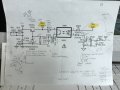
Here it is..my nemesis....
1. no stb voltage......short somewhere.....
2. V810 needs a voltage on base to turn on..right? Allowing opto diode to shine.....passing 12v collector to emitter....right?
3. Why does V820 bring 16V from collector to emitter..already at 153V AC?
4. why does vz812 have both AC & DC even with C824 and C826?
5. note the different voltages on R827 at different power ups....?
6. Why couldn’t I have picked an easy hobby!
Attachments
-
 2.5 MB Views: 42


