Lambda PS Operator Manuals

Thread Starter

doug3460

Joined Oct 19, 2008
87
Is there an internet source for finding a PDF or equivalent manual for this PS circa 1994 (my best guess)

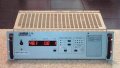
I purchased a MIL Surplus Lambda Standard Power System. It has x2 LNS-Z-5-OV & x2 LNS-Y-15 supplies. It works nicely, however, I am clueless about the the Fault set-up, all the connections on the back (besides the obvious ones), etc..

I have searched the net for a day trying to find an operator's manual, but have had no success except possibly one on ebay, but it doesn't specify which system it's for, so that's no help.

Any suggestions or instructions would be appreciated. As always, thanks for your time.
 

SgtWookie

Joined Jul 17, 2007
22,230
Try here:
http://www.lambdapower.com/products/legacy_products.htm
If no results, call 1-800-LAMBDA-4 for assistance.
[eta]
I have an old Lambda LDS-P-03 I picked up as surplus for $30. 0-32VDC @ 2.7A. It's a great old linear supply. They originally sold for around $600. I swapped out the original internal Vadjust pot with a 20k Bourns 10-turn "knobpot", and added banana jacks for the +V, -V, and external sense lines, along with an internal power switch and fuseholder. The hands on the knobpot's dial indicate volts and 10s of volts within 250mV over the full range, which now extends to 50+vdc.
 
Last edited:

Thread Starter

doug3460

Joined Oct 19, 2008
87
Thank you Beenthere & Sgt Wookie for the replies.

I had searched most of those sites from Google & Lambda (which is how I figured out what units were in the case, the name "standard power supply" & approximate era it was assembled). However, the search this time led me to the pictures I've attached.

My supply is very similar to what's shown, except of course I have 4 PS, two at 5V ±5% & two at 15V ±5%.

My supply back is different in that I have two output panels & only one "man killer" power hook up. But the output panel shown emulates mine - each panel has 2 +V/-V posts and the (I think) remote sensor hook-ups (the white terminals at the top).

I will write Lambda & see if they can help me track down a user's manual.

OT: Sgt Wookie - the modifications you mentioned interest me. I was going to just run hook-up wires off the +V/-V terminals to binder posts in a dummy panel for my banana plugs. Since the PS is for breadboard work primarily below 15V, I was thinking I could just add some voltage limiting circuit to get down to 13.8V (i.e., something w/ a 317IC).

Should I consider replacing the voltage adjusters on the front panel of the PS a knob as you've done? I have read/heard that this linear supply is a very nice one & was pretty expensive in it's day (btw, got mine for $30 too) - I'd hate to goof it up.
 

Attachments

SgtWookie

Joined Jul 17, 2007
22,230
Sgt Wookie - the modifications you mentioned interest me. I was going to just run hook-up wires off the +V/-V terminals to binder posts in a dummy panel for my banana plugs. Since the PS is for breadboard work primarily below 15V, I was thinking I could just add some voltage limiting circuit to get down to 13.8V (i.e., something w/ a 317IC).
Well, an LM317 has a minimum 1.7v dropout; therefore if your Vin is 15, the most you could get out of an LM317 would be 13.3v. There are "low dropout" regulators on the market nowadays, some have a much lower dropout than others; down to 0.4v. The thing with linear regulators is, that for a given output current, the power dissipation in the regulator increases as your output voltage decreases.
P = I(Vin-Vout), or Power Dissipation in Watts = Current in Amperes times (Voltage In - Voltage Out)
Adding an external regulator can be done, but your output regulation & stability will then be dependent upon your external regulator design.

Should I consider replacing the voltage adjusters on the front panel of the PS (with) a knob as you've done? I have read/heard that this linear supply is a very nice one & was pretty expensive in it's day (btw, got mine for $30 too) - I'd hate to goof it up.
My supply was kind of a special case. It was designed as a variable power supply, but the Vadj was a pot inside the case with a screwdriver slot, and no voltmeter. Adding a precision knobpot gave me considerably finer voltage adjustment capability (10 turns vs 3/4 turn), along with a direct mechanical readout that corresponds remarkably closely to the actual Vout. Besides, I need no tools to adjust the voltage anymore.

There is always a risk that you'll damage something if you open it up. My supply is quite a bit more simple than yours is, and I have a goodly number of years tinkering with these kinds of things. You'll have to carefully consider the possible benefits vs risks.

I suggest that you put off any internal modifications for the present time.
 
Top