
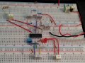
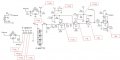
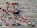
I'm trying to build a variation of this project: I really just want the detector portion of the project so I can detect a small fast object moving through a "screen". I have built the attached circuit on my breadboard including the exact components specified. When I power up the circuit, the output LED stays lit continuously. If I shade the LED/PD section of the circuit from ambient light, the output LED will go out, but then nothing triggers the PD output into my amplifier circuit.
The IRLEDs output at 880 nm while the PD peak sensitivity is 940 nm. I was thinking this was far enough into the IR spectrum that ambient light would not play a major factor. I'm a ME not a EE, so my EE skill are pretty weak! Any assistance would be greatly appreciated.
-Capel
The IRLEDs output at 880 nm while the PD peak sensitivity is 940 nm. I was thinking this was far enough into the IR spectrum that ambient light would not play a major factor. I'm a ME not a EE, so my EE skill are pretty weak! Any assistance would be greatly appreciated.
-Capel
Attachments
-
 88.6 KB Views: 65


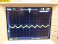
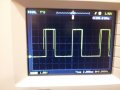


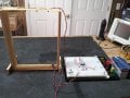

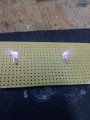
") What do you think about the PD? (There is a picture in post #9 of this thread.) As you can see from the first photo in post #13, the PDs are facing down so no direct light is hitting them. I've also included a close-up of the PDs in the frame.
What do you think about the PD? (There is a picture in post #9 of this thread.) As you can see from the first photo in post #13, the PDs are facing down so no direct light is hitting them. I've also included a close-up of the PDs in the frame.


