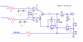
Instrumental Amplifier (AD620) circuit is not giving correct output

Thread Starter

Samia Riaz

Joined Apr 5, 2022
11
hi SR,
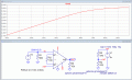
Checking your circuit with a Ramp input signal, you cannot get a Vout swing greater than Vcc -1.2V, check this clip from the datasheet.

The circuit is no good.
E

Added:
Sim using +/- 5mV test signal, the limits of Vout are plotted.
View attachment 264807
View attachment 264806
Sorry for the delay, thank you for the replies it was very helpful. According to the datasheet output swing is Vs-1.2 Volts. In our case, Vs is 5 volts so output should be around 3.8 volts but the maximum output we are getting is 4.12 volts. Is it okay?
 

ericgibbs

Joined Jan 29, 2010
21,517
hi SR,
The Vs-1.2v is only a typical value, a value of 4.12v is possible.

What is your Input signal voltage source.?
More information about the project would be helpful.
E
 

Thread Starter

Samia Riaz

Joined Apr 5, 2022
11
hi SR,
The Vs-1.2v is only a typical value, a value of 4.12v is possible.

What is your Input signal voltage source.?
More information about the project would be helpful.
E
We are taking power from Arduino and using resistors of value 460 ohm to divide it as shown in circuit diagram attached below.
 

Attachments

ericgibbs

Joined Jan 29, 2010
21,517
hi SR,
So you are powering the AD620 from a voltage divider.?
That could be a problem.
I will post a simulation based on that power supply method.
E

Update: @Samia Riaz
You require a low impedance source for the Vref, check the non-linearity of the Vout.
Also, by choosing a Vref of 2.5v, the maximum input signal will be approx 3mV max before you reach Vout saturation.

What is the purpose of the AD620 project.?
What will be the Input signal voltage range when the project is in operation.??
also, what will be the required Vout range for the project.?

EG 1566.gif
 
Last edited:

Thread Starter

Samia Riaz

Joined Apr 5, 2022
11
hi SR,
So you are powering the AD620 from a voltage divider.?
That could be a problem.
I will post a simulation based on that power supply method.
E
Looking forward to see simulation results. If the current from the voltage divider is giving enough signal to power AD620 so what can be potential issues??
 

eetech00

Joined Jun 8, 2013
4,716
hi ee,
Check the settings of the TS's supply and Vref settings, they have been tweaked to give a steady state Vout of approx 3.8v and it is Vmax limit. my post #7.

I have set the Vcc and Vref to 2.5V, so that Vout sits at approx +2.5Vout my post #8.

Note the Table for the AD620 on that post.

E
Try reading your own posts.
 

ericgibbs

Joined Jan 29, 2010
21,517
I have set the Vcc and Vref to 2.5V, so that Vout sits at approx +2.5Vout my post #8.
hi ee.
You still have not got it right.:rolleyes:
When you set Vcc =2.5V and Vref to 2.5V, [which are clearly shown in ALL the images as being series connected]
Adding 2.5v + 2.5V =5V.

Please read and try to understand what has been posted.
E


Thread Starter

Samia Riaz

Joined Apr 5, 2022
11
hi SR,
So you are powering the AD620 from a voltage divider.?
That could be a problem.
I will post a simulation based on that power supply method.
E

Update: @Samia Riaz
You require a low impedance source for the Vref, check the non-linearity of the Vout.
Also, by choosing a Vref of 2.5v, the maximum input signal will be approx 3mV max before you reach Vout saturation.

What is the purpose of the AD620 project.?
What will be the Input signal voltage range when the project is in operation.??
also, what will be the required Vout range for the project.?

View attachment 265027
We are using it for designing an EMG circuit. The limitation is that we need to power and read it using an arduino. So, we only have 0-5V input voltage and we can read it in the same range also. Are there any better alternatives to voltage divider for our case??
 

Thread Starter

Samia Riaz

Joined Apr 5, 2022
11
hi SR.
Post a diagram of your muscle pads and input circuit to the AD620.
You should have two muscle pick up pads which are the Differential input to the AD620 and one pad for the Mid-voltage point connection, which is at Vref.

E

Update:
Read this link. Patient Protection Circuit.
https://www.biosemi.com/faq/limit_current.htm
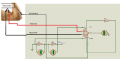
The picture below shows circuit diagram including EMG data pads connections.
 

Attachments

ericgibbs

Joined Jan 29, 2010
21,517
hi,
What is the purpose of the two 470 Ohm resistors across the two 2.5V supplies.?
E

Update:
Are you using just a single 5V supply and using that 470R divider to give 2.5V?
If yes, that method will cause problems, Vref must be from a low impedance source, usually the output of an OPA.
 
Last edited:

Thread Starter

Samia Riaz

Joined Apr 5, 2022
11
hi,
What is the purpose of the two 470 Ohm resistors across the two 2.5V supplies.?
E

Update:
Are you using just a single 5V supply and using that 470R divider to give 2.5V?
If yes, that method will cause problems, Vref must be from a low impedance source, usually the output of an OPA.
We are dividing 0-5 volt voltage with their help. This gives us 0-2.5-5V. Taking 2.5 as reference, 0 becomes -2.5 and 5 becomes 2.5V
 

Thread Starter

Samia Riaz

Joined Apr 5, 2022
11
hi SR,
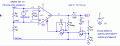
This is an example of an EMG, note the Vref.
E
View attachment 265209
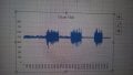
Sorry for the delay and thank you for the reply. We have tested this circuit with reference 2.5V and output is shown in the picture below. Do we need to add a patient protection circuit in this EMG circuit? Is this necessary? How can we add protection circuit with reference 2.5V?
 

Attachments

Thread Starter

Samia Riaz

Joined Apr 5, 2022
11
1. According to the standards in the link you gave ( https://www.sciencedirect.com/science/article/pii/S1388245719311782 ), the maximum leakage current should be 10mA. Our circuit leakage current w.r.t ground was 1.6uA using the method shown in this link (https://electrical-engineering-port...easurement-techniques-leakage-ground-currents).
2. Then we tried patient protection circuit using diodes shown in the image attached below using this link (https://www.picotech.com/library/ap...iogram-ecg-circuit-for-use-with-oscilloscopes)
but our results were not good.
3. Below are the circuit results without protection circuit=
Input Voltage: 5V
Reference Voltage: 2.5V
Input current: 4.8mA
Reference current: 0.097mA
leakage current w.r.t ground: 1.6uA
We are using single supply so our reference voltage is 2.5V and when this reference is shorted with electrodes the short current range is 0.05u-0.2uA. Is this circuit safe without protection circuit? What is the worst case scenario?
 

Attachments

ericgibbs

Joined Jan 29, 2010
21,517
hi Samia,
In what way do you plan to use this EMG.?
Is it a one off project for demonstration use, or do you intend to use the device in some other way.??

E
 

Audioguru again

Joined Oct 21, 2019
6,826
The power supply for this medical device is supposed to be certified to be isolated from electricity voltages and from earth ground. Then if the patient is accidently connected to ground he is not conducting electricity and earth-grounding the Ref does not change its +2.5V to 0V.
 
Top