input impedance of source follower

Thread Starter

screen1988

Joined Mar 7, 2013
310
Do you need to calculate both input impedances for large signal and small signal?
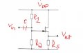
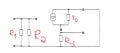
For example, in the source follower below.

With small signal, I can figure out its input impedance is R1//R2 but I don't know why books don't mention about larger signal input impedance.
(With large signal, the input impedance is infinite.)
 

Attachments

Last edited:

Thread Starter

screen1988

Joined Mar 7, 2013
310
What makes you think this is true? The resistors are still connected to the input.
I meant this is small signal model. Sorry for the confusion. I have added "(With large signal, the input impedance is infinite.)".
This is only an additional information that I want to make clear not accompanying with image.
 

Ron H

Joined Apr 14, 2005
7,063
I meant this is small signal model. Sorry for the confusion. I have added "(With large signal, the input impedance is infinite.)".
This is only an additional information that I want to make clear not accompanying with image.
You didn't explain why you think the input impedance changes.
 

Thread Starter

screen1988

Joined Mar 7, 2013
310
You didn't explain why you think the input impedance changes.
Uhm...I think I know what you mean by now. You mean that input impedance doesn't include R1 and R2?
If so, because Ig = 0 => input impedance is infinite in both cases.
But I am a bit confused. To make transistor operates in saturation mode we have to bias.
Source follower is used as a voltage buffer. It has to have a large input impedance. But in this case we add R1 and R2 to bias, the input impedance of entire circuit is no longer infinite but R1//R2.
 

t_n_k

Joined Mar 6, 2009
5,455
Uhm...I think I know what you mean by now. You mean that input impedance doesn't include R1 and R2?
If so, because Ig = 0 => input impedance is infinite in both cases.
But I am a bit confused. To make transistor operates in saturation mode we have to bias.
Source follower is used as a voltage buffer. It has to have a large input impedance. But in this case we add R1 and R2 to bias, the input impedance of entire circuit is no longer infinite but R1//R2.
When you refer to large signal what do you mean?

The second diagram looks more like a conventional small signal model.

Presumably you aren't confusing the DC bias requirements with the large (small?) signal amplifier case ...????
 
Last edited:

Thread Starter

screen1988

Joined Mar 7, 2013
310
When you refer to large signal what do you mean?
I think I should mention that that it is DC bias.
Vout = Vout (dc) + Vout (ac)
If I consider a circuit including R1, R2, Rs and NMOS.
With DC bias: input impedance is infinite
With AC signal: input impedance is R1//R2
I see that in many books say that source follower has infinite impedance. I want to know why. I took the circuit above to analyse and calculated input impedance but it seems correct.
 

t_n_k

Joined Mar 6, 2009
5,455
The usual practice is to include the input bias networks in the overall analysis of an amplifier - which includes such matters as input impedance. Clearly, if one considers the case of the impedance (or resistance) seen looking only into the gate, then the expectation is that one would see a very high value - effectively infinite in an ideal situation. This is the true whether one is considering a AC or DC source or "signal" driving the gate terminal.

If one includes the biasing and decoupling components in the analysis, then the outcome will be different. Clearly the (ideal) coupling capacitor will block any DC current anyway, so the DC input resistance seen at the capacitor input terminal must of necessity be infinite. Since the coupling capacitor can pass AC current then the AC input impedance seen at the same input point will not be infinite when the bias network is taken into consideration.

One should however keep in mind that there are parasitic capacitances & resistances in any real device and these may become significant in relation to input impedance in certain circumstance - such as one encounters in high frequency amplifier modelling.
 
Top