
Hi,
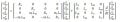
From literature the induction motor has been well described in state space, see attachment- Induction Motor-01.jpg:
This equation describes the induction motor with a rotating rotor.
To describe a rotating stator as a consequence of the 3 phase supplied power, the following equation can be used, see attachment - induction motor - rotorary frame -02.jpg:
Now, my question is the following:
I have a little difficulty understanding the second equation, the one showing the inclusion of the rotorary stator frame.
Because when I simulate a power supply (through the use of 3 combining 3 sine waves set 120 degrees apart)
\(
3 phase = A*(sin(\omega t+\theta) + sin(\omega t+\theta+2\pi/3) + sin(\omega t+\theta - 2\pi/3))
\)
then I can control the amplitude by adjusting A and the speed by adjusting f within \(\omega\) and any start angle by \(\theta\).
This should give me control of the motor by adjusting its power supply and I would not need the rotorary frame reference?
On the other hand if I use the rotorary frame reference I only need to control the amplitude of the signal and the speed within the stator, right?
Are my last statements true?
cheers,
Attachments
-
 18.2 KB Views: 49
 -
 23.4 KB Views: 46


