Facebook
 Google
 GitHub
 Linkedin

Hello, I am building an intermediate frequency amplifier for a class project and I've run into a bit of a problem. This IF amplifier is supposed to be built for 455 kHz with a 10 kHz bandwidth. For this project I can only use transistors and IF transformers or filters. Also, my circuit has to be powered by a 9 volt battery. I'm in a group and we are building an AM receiver as a whole so I will be receiving a small AM signal. I'll go ahead and show what I've done so far and then state what my problem is.
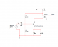
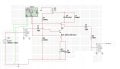
At the moment I'm just working on the amplification portion of the 1st stage IF amplifier. Once I get the amplification working right, I plan on adding an IF transformer to both the input and output, as is shown in the paint edit, and adjusting the internal impedance to get the required bandwidth.
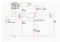
I will now go through the calcs I've done to get the values shown in my document labeled multisim. I have an inductance of 480uH and a Capacitance of 254.9 pF at the collector because 2*∏*f=1/√(L*C). Using these values gave me a f of 455 kHz which is what I need. I later hooked up a bode plotter and saw that the peak of my bode plot was at 455 kHz as it should have been.
When I originally designed this circuit, I had it constructed in such a way that the AC output was over 10V pk to pk. After talking to my professor, I decided to make the output 9V pk to pk. To do this, I realized I would need my Q point to be at the center so I first chose an Re of 300Ω and then calculated my needed Icq to be 12.85 mA. I did this using the equation Vcc=Ic*(Re+Rc)+Vce. As Vce goes to 0, the circuit is in saturation, my Vcc was 9V, my Re was 300Ω, and I said that my Rc was 50Ω because of the internal resistance of the inductor.
The β of my transistor is 155, which I edited in multisim, so I found my needed ibq to be 82.9 uA. I made a voltage loop and came up with the equation Ibq=(Vbth-Vbe)/(Rbth+hie+Re*(β+1)), where Vbth is the equivalent Thevenin voltage and Rbth is the equivalent Thevenin resistance. I solved for hie using the equation hie=Vt/Icq*β, where Vt is 25mV. This gave me a value of hie to be 301. I then chose a value of Vbth to be 4.7V and found the Rbth to be 1,150Ω. By using the equations Rbth=R1||R2 and Vbth=Vcc*R2/(R1+R2), I found R1 to be 2200Ω and R2 to be 2400Ω.
To find my RL, I used the equation VceAC=Vce+Icq*RAC. I was thinking that RAC would be just my RL, but I'm now wondering if I perhaps need to include some different internal resistance from my inductor capacitor couple since they are at resonance. Considering my RL to be the only AC resistance, I found it to be 350Ω.
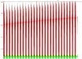
The big problem that I foresee at the moment, is that when I simulate in multisim, my output voltage gradually increases and never seems to cease increasing. I'm not sure why this is.
At the moment I'm just working on the amplification portion of the 1st stage IF amplifier. Once I get the amplification working right, I plan on adding an IF transformer to both the input and output, as is shown in the paint edit, and adjusting the internal impedance to get the required bandwidth.
I will now go through the calcs I've done to get the values shown in my document labeled multisim. I have an inductance of 480uH and a Capacitance of 254.9 pF at the collector because 2*∏*f=1/√(L*C). Using these values gave me a f of 455 kHz which is what I need. I later hooked up a bode plotter and saw that the peak of my bode plot was at 455 kHz as it should have been.
When I originally designed this circuit, I had it constructed in such a way that the AC output was over 10V pk to pk. After talking to my professor, I decided to make the output 9V pk to pk. To do this, I realized I would need my Q point to be at the center so I first chose an Re of 300Ω and then calculated my needed Icq to be 12.85 mA. I did this using the equation Vcc=Ic*(Re+Rc)+Vce. As Vce goes to 0, the circuit is in saturation, my Vcc was 9V, my Re was 300Ω, and I said that my Rc was 50Ω because of the internal resistance of the inductor.
The β of my transistor is 155, which I edited in multisim, so I found my needed ibq to be 82.9 uA. I made a voltage loop and came up with the equation Ibq=(Vbth-Vbe)/(Rbth+hie+Re*(β+1)), where Vbth is the equivalent Thevenin voltage and Rbth is the equivalent Thevenin resistance. I solved for hie using the equation hie=Vt/Icq*β, where Vt is 25mV. This gave me a value of hie to be 301. I then chose a value of Vbth to be 4.7V and found the Rbth to be 1,150Ω. By using the equations Rbth=R1||R2 and Vbth=Vcc*R2/(R1+R2), I found R1 to be 2200Ω and R2 to be 2400Ω.
To find my RL, I used the equation VceAC=Vce+Icq*RAC. I was thinking that RAC would be just my RL, but I'm now wondering if I perhaps need to include some different internal resistance from my inductor capacitor couple since they are at resonance. Considering my RL to be the only AC resistance, I found it to be 350Ω.
The big problem that I foresee at the moment, is that when I simulate in multisim, my output voltage gradually increases and never seems to cease increasing. I'm not sure why this is.
Attachments
-
 125.6 KB Views: 75
-
 113.7 KB Views: 56
-
 99.8 KB Views: 41