
please help me
this circuit is not working prperly
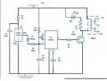
the output at pin 3 is not getting high when input at pin2 is getting low
ICNE555 is configured in monostable mode.
this circuit is not working prperly
the output at pin 3 is not getting high when input at pin2 is getting low
ICNE555 is configured in monostable mode.
Attachments
-
 52.2 KB Views: 36
")


