I want a detail explanation of the circuit like how the bjts and capacitor works.

Thread Starter

saad sami

Joined May 9, 2018
1
There's an intercom circuit here:

http://ee.old.no/library/EE1003-en.pdf

You can build from scratch as shown in the manual, or you can buy a ready assembled audio amplifier module and add the changeover switching and speakers. Or for less assembly work than the EE circuit - you could build your own audio module with one of the many audio chips that are available.

The one in the Philips kit uses the speakers to double as the microphone, the amplifier uses a common base input stage for its low input impedance to match better to the speaker. This is a neat trick that you could add on to any of the other options.
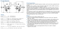
i want a detail explanation of below circuit like how the bjts and capacitor works


Mods Note:
Please don't hijack other member's thread.
This thread was split from -- Intercom System.
 

Attachments

Last edited by a moderator:

-live wire-

Joined Dec 22, 2017
959
It probably uses the BJTs as op amps to amplify a small signal. The caps and resistors probably are used to make a filter. But some context here would help a lot.
 

OBW0549

Joined Mar 2, 2015
3,566
It probably uses the BJTs as op amps to amplify a small signal.
Just FYI, "op amp" is NOT a generic term synonymous with "amplifier." It refers to a specific type of amplifier with differential inputs, almost always integrated on a chip. Saying that the BJTs in the TS's circuit are being used "as op amps" is a gross misuse of the term.
 

-live wire-

Joined Dec 22, 2017
959
Just FYI, "op amp" is NOT a generic term synonymous with "amplifier." It refers to a specific type of amplifier with differential inputs, almost always integrated on a chip. Saying that the BJTs in the TS's circuit are being used "as op amps" is a gross misuse of the term.
Sorry. My bad.
 

Janis59

Joined Aug 21, 2017
1,849
What exactly are those things unclear??
The role of first bjt?? Thats for bias stabilisation. The role of second transistor? Thats for amplifying.
The capacitor betw C and B?? Thats for biasing will be stable instead of shivering in phase with the input signal. The tumbler? Thats for commuting who is speaking and who is listening.
By the way, better is search for duplex circ what dont demand to push any button, like modern telephone do. One of elegant solution there is the circulator circ by means of opamps. Or simpler - with negative loop transformer like WW2 telephones was used to do.
 

AnalogKid

Joined Aug 1, 2013
11,038
What exactly are those things unclear??
The role of first bjt?? Thats for bias stabilisation. The role of second transistor? Thats for amplifying.
Incorrect, twice.

The role of the first transistor is voltage amplification. The role of the second transistor is current amplification.

ak
 

Janis59

Joined Aug 21, 2017
1,849
RE: Analog Kid
Do You are sure that large electrolythic capacitor between input and output may give anything larger than one point zero zero??
If it would be the ordinary small ceramic compensation capacitor, as for many amplification cascades bay have, the symbol would be like normal capacitor.

But to put point the disputs, one may easily draw the model into LT-Spice and get a simulation. OK, I shall make it in next few minutes.
 

Janis59

Joined Aug 21, 2017
1,849
OK, Im ready with model.
I put into it the 12V Vcc and 100K and 100K and 10K and load 8 Ohm. The cap I used in two scenarios, the 1000p and 1000u (as it was drawn electrolyte). Result. In small capacitor mode U input 0,18 V 50 kOhm 180 uA, Collector of first bjt 10V & 19 mA, load 11V & 40 mA.
In electrolyte mode - for first bjt K(u)=1, thus the all gain comes out from second bjt.
 

AnalogKid

Joined Aug 1, 2013
11,038
The only large electrolytic is C1, which is power supply decoupling. C2 is high frequency rolloff to prevent oscillation. C3 is an input coupling capacitor so the speaker's low DC resistance does not mess up the biasing of Q1.

C1 is the only electrolytic, which is why it has a + sign to indicate its polarity. C2 and C3 are not electrolytic capacitors. Your statement that the symbol is not like a "normal capacitor" is incorrect. There is more to the world of electronics than your personal experience base. That is the way all capacitors were drawn 50 years ago in schematics from Zenith, RCA, Sams, etc.

And again, the 2nd transistor does not provide any voltage gain; it is an emitter follower.

ak
 

OBW0549

Joined Mar 2, 2015
3,566
In electrolyte mode - for first bjt K(u)=1, thus the all gain comes out from second bjt.
WRONG.

The only reason you obtained a voltage gain of 1 for the Q1 stage is your choice of resistor values for R1 and R2; with those two resistors equal, the gain is ≈1. Change R1 to 5 kΩ, and the gain will go up to ≈20.

It should be easy to see, on inspection, that the Q1 stage is operating similarly to an ordinary inverting op amp amplifier configuration, where the gain is set by the ratio of the feedback resistor (R2) to the input resistor (R1).

Q2 is operating as an emitter follower, to provide current to drive the speaker.
 

AnalogKid

Joined Aug 1, 2013
11,038
In the drawing posted by AG, R1 is 1K and R2 is 1M, for a very large gain. Q1 is essentially running "wide open", with a little bit of DC bias stabilization. C2 is 47 pF, for a lowpass corner frequency of 3.4 kHz, a typical voice bandwidth that reduces a lot of higher frequency noise and interference.

ak
 

Sensacell

Joined Jun 19, 2012
3,445
Do we believe this thing actually functions?

It looks like a classic internet 'Bad Circuit" to me, not really a viable design.
It will be hopelessly sensitive to transistor beta, which varies over a large range, device to device.
Not to mention the large amount of distortion caused by non-linear amplification.
 

Audioguru

Joined Dec 20, 2007
11,248
I simulated the "bad circuit" using a BC847A that has a typical hFE of 180 but 110 is its minimum. It is barely turned on with severe distortion and does not conduct enough to turn on the output darlington transistor. A BC847C has a typical hFE of 520 and it works a little better.

The BC847 has the same chip as a BC547 used in the circuit but is in a smaller case. The hFE of a BC547 is from 110 to 800.
 

Attachments

Top