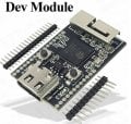
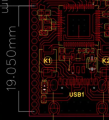
how to test 1.27 mm pitch board?
- Thread starter LAOADAM
- Start date
Scroll to continue with content
ronsimpson
- Joined Oct 7, 2019
- 3,257
Sorry, it is 1.27mm, I just changed it, not change title yet.At digikey.com they show these options for pin headers. I do not see 1mm.
View attachment 320684
I found the board you show. It would have ben better to say what the board is. It is 1.27mm.
View attachment 320685
Since what you usually do doesn't match this board, don't insist on doing what you usually do. Instead, work with a board that is 1.27 mm pitch.
It's hard to suggest anything more specific since we have no idea what YOU mean by "test" the board, or what it is that you "usually" do.
Perhaps the most obvious route would be to simply make an adaptor board that this module plugs into and that then has pins on a 2.54 mm pitch to match what you usually do.
MisterBill2
- Joined Jan 23, 2018
- 19,588
Now the question is "What do you mean by test?" and what sort of production rate is required??
What I think I see is a PCB with two rows of locations for connector pins, and two connectors for external cable plugs. Certainly with the correct fixture all of the connections can be made using spring loaded pins, available from a few sources.
Automated loading could be done by an XYZ gantry robot using a magnet to pick up the steel connector shields.
Probably an automated unload with a human operator load will be the way to go, with an automatic unload for "Accept" and a manual unload for reject. I have done that scheme for quite a few testers over the years.
Operation of the two push-button switches is a separate issue that I have not addressed.
The software to do the test is an entirely separate discussion.
Last edited:
You May Also Like
-

Microchip’s New Plug-and-Play Bluetooth Solutions Lower RF Design Barriers
by Mike Falter
-

Startup Orca Semiconductor Exits Stealth Sampling Its First PMIC
by Jake Hertz
-

Nuvoton’s New MCU Balances Low Power Consumption and Speed
by Jake Hertz
-

Switching Losses in Bipolar Junction Transistors
by Robert Keim


