How to sync to NTSC color burst (3.58MHz sine wave that only lasts for 9 cycles every 63 microseconds)

Thread Starter

mpownby

Joined Oct 7, 2016
18
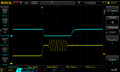
I need a digital clock (ie square wave) that is in sync with the color burst (3.58 MHz sine wave) from an NTSC composite signal (see attached picture). One challenge is that this sine wave is only present for about 9 cycles every 63 microseconds, due to the way NTSC is designed. I need to be able to refer to this clock at any time, not just while the color burst is active. I know that this is a solvable problem since every analog TV set has an internal circuit to solve this problem. Unfortunately, I've had a very difficult time finding answers by googling, partly because most of the resources I find seem to assume some basic knowledge that I lack.

I've already determined that an LM1881 can help with this as it will indicate approximately when the color burst is active. I also assume that I will need some kind of phase locked loop, but I'm not sure how to take advantage of this, since it's my understanding that every PLL has some delay relative to the original clock it is mimicking (how to compensate for the delay?). I'm also not sure how to detect the difference between the sine wave itself and just random analog noise.

I've bought a few books on basic analog electronics, and am willing to do some reading, but I could use some pointers in the right direction to help me focus.

Any help is appreciated.
 

Attachments

MrChips

Joined Oct 2, 2009
30,802
You need a PLL built around a 3.579545MHz color burst crystal oscillator.
The PLL will lock on to the phase of the incoming color burst and will stay in phase until the next color burst signal is received 63μs later.

1654140507380.png
 

Thread Starter

mpownby

Joined Oct 7, 2016
18
This IC many work for you (if you can find a source for it).
crutschow, I wonder if you have any experience using this IC that you linked me to? I built a prototype to test it but no matter what I send to it (including a fixed 3.58 MHz wave from a frequency generator) it seems to just ignore the input. It will output rather shaky 3.58 MHz / 14.3 MHz waves. It looks like the only things that I can really change are the quality of crystal and the trimmer cap. I can't find anything in the data sheet that explains how the trimmer cap is intended to be adjusted so I have to assume that it was so obvious that they didn't feel like an explanation was needed. But I'm in the dark here.
 

crutschow

Joined Mar 14, 2008
34,420
, I wonder if you have any experience using this IC that you linked me to?
Unfortunately, no.
I can't find anything in the data sheet that explains how the trimmer cap is intended to be adjusted
It should be adjusted to get a stable output frequency.

How is the circuit constructed?
It likely won't work on a plug-in type breadboard due to the large stray capacitance of such a board..
 

seanstevens

Joined Sep 22, 2009
253
but no matter what I send to it (including a fixed 3.58 MHz wave from a frequency generator)
I presume you have fed a properly terminated video signal into it? As well as the required voltage/signal into pin 7? I have no experience with this particular chip but back in the day of analogue days, I played with a bit of video decoding. But then there were many dedicated chips for that, one of which was LM1881.
I am not sure the quality of crystal/trimmer would be that critical, I think the chip may be looking for proper levels of vide, sync etc. before it works properly. And as mentioned above, breadboarding Mhz critical signals is not a good idea.
 
Last edited:

Thread Starter

mpownby

Joined Oct 7, 2016
18
Thanks guys, for the help!

I've attached the schematic and board layout to hopefully answer your questions, as well as a pic of the prototype that I assembled. I admit, I come from the digital side of things and forgot about potential noise issues when doing this first prototype, so I'm sure I've got issues there (I've got several digital ICs). The problem is I am quite ignorant about proper analog techniques so any fixes I'd do would just be guessing at this point. Any advice would be appreciated.

seanstevens, I am embarrassed to admit that I don't know what "properly terminated" would look like for a video signal. I've used the LM1881 for years and it seems pretty tolerant of any video signal I've fed into it (from a Raspberry Pi or a laserdisc player, for example).

The crystal I am using is: https://www.digikey.com/en/products/detail/raltron-electronics/AS-14-31818-20-SMD-TR/10271760

And the trimmer I went with is https://www.digikey.com/en/products/detail/sprague-goodman/GKH25000/5278250 mainly because it was one of the only ones I could find with the suggested capacitance range of 5pF-25pF; I'm not even sure if I installed it correctly and I don't know what tool I'm supposed to use to adjust it as the slot that apparently is used for adjusting is too small for anything I've got on hand. I emailed the manufacturer but no response :(
 

Attachments

ag-123

Joined Apr 28, 2017
276
here is an idea, even though there is *no assurance* if it'd even work
STM32 F405/F407 and some of the STM32F4xx microcontrollers has 3 ADCs which can go up to 2.4 msps each
https://www.st.com/en/microcontrollers-microprocessors/stm32f407-417.html#overview
in one of the more obscure triple ADC modes, it could possibly reach combined sampling rates of 7.2 msps
this is just about the Nyquist limit.
At those speeds, it may be possible to digitally process the video signals and possibly digitally 'scan convert' them on the fly.
This is quite extreme, i've not literally tried it, i'd guess it'd still take quite a bit of DSP tricks to correctly 'sync' the frames on the fly.
 

Thread Starter

mpownby

Joined Oct 7, 2016
18
Thanks for the idea. At this point, I'd prefer to try to get my existing design working since I feel like it's close if I can just figure out what I'm doing wrong with this MC44144 chip.

here is an idea, even though there is *no assurance* if it'd even work
STM32 F405/F407 and some of the STM32F4xx microcontrollers has 3 ADCs which can go up to 2.4 msps each
https://www.st.com/en/microcontrollers-microprocessors/stm32f407-417.html#overview
in one of the more obscure triple ADC modes, it could possibly reach combined sampling rates of 7.2 msps
this is just about the Nyquist limit.
At those speeds, it may be possible to digitally process the video signals and possibly digitally 'scan convert' them on the fly.
This is quite extreme, i've not literally tried it, i'd guess it'd still take quite a bit of DSP tricks to correctly 'sync' the frames on the fly.
 

Thread Starter

mpownby

Joined Oct 7, 2016
18
Ok, I've made good progress and got the MC44144 basically working (HINT: my problem was that I wasn't adjusting the trimmer cap properly). What I'm still getting hung up on is properly converting the 4x FSC wave into a nice TTL-compatible square wave.

Here is what the wave looks like output from pin 5 (the teal wave that is triangular in shape!)
DS1Z_QuickPrint23.png


Then when I run that through this circuit from the datasheet:
mc44144_ttl.png

Then the resulting wave looks like this (teal wave!):
DS1Z_QuickPrint24.png


It's almost usable but the wave form keeps "dipping down" on the rising edge and it's going low enough that this could register as low by accident.

Can someone point me in the right direction to reliably solve this problem?
 

WBahn

Joined Mar 31, 2012
30,052
I just noticed this thread and haven't done more that just skimmed it. If it hasn't already been suggested, then you might look at the concept of injection-locked oscillators and look into how they were used in the early color TV sets to do exactly what you are attempting to do.
 

sparky 1

Joined Nov 3, 2018
757
Like conceiving basic radio for example you might need some idea about the transmitter and the signal.
So. with color TV composite signal it is helpful to get some idea about what the color TV camera outputs what happens after.
What was transmitted from the older television station along with the color burst signal that provides a way to reassemble NTSC.
There is an order and distinction about what the different processes do. Since it is complex it is not easy to keep everything straight.

The use of a vector scope simplified alignment and testing of the composite signal and the use of color burst shown in video on the vector scope.
Having the vocabulary fresh in mind and the concepts for these various functions and where they originate can help you answer your own question.

video at time 13:32
 
Last edited:

WBahn

Joined Mar 31, 2012
30,052
In conceiving basic radio you might need some idea about the transmitter and the signal.
So. with color TV composite signal it is helpful to get some idea about what the color TV camera outputs what happens after.
There is an order and distinction about what the different processes do. Since it is complex it is not easy to keep everything straight.
Having the vocabulary for these various functions and where they originate might help you to answer your own question.

video at time 13:32
Thanks. Nice video. I already knew a lot of this history, but it helped fill in a number of underlying gaps (not all) in my understanding pretty nicely.

As an aside, I personally like the presentation style here. Simple, give-me-the-facts-and-explain-them. No fancy animation or gimmicks or eye candy. Hard to find anything comparable today -- everything has to have people jumping up and down and screaming and pictures flashing all about and cutesy cartoon overlays. No thank you.
 

sparky 1

Joined Nov 3, 2018
757
Thanks WBahn, I remember at age 9 reading explanation about color burst in popular electronics, but parts were left out.
I also left out the quantitative vector system because my explanation would be a real mess.

The technical writers and the engineers of that era had to be polished and very accurate with the material. The video went from concept illustration then it cut to a non-technical approach to vector math and straight into showing the test bar on the vector scope which also showed the color burst conveniently located at it's RB-Y = zero location.

All about electronics follows that same tradition needed for academic electronics. Those who really want to know and are willing to search but the search engines are not able to filter out the pass the exam fluff.
 
Top