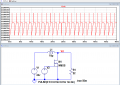
How to monitor MOSFET source voltage

ericgibbs

Joined Jan 29, 2010
18,840
hi pp,
What sort of question is that.??
A lot more information is required in the question, if we are not to waste more of our time guessing.

If you have a draft circuit, post it.
E
 

ericgibbs

Joined Jan 29, 2010
18,840
I want to monitor the voltage at the source terminal of the MOSFET.
It is always 0v Gnd

Update:
You originally posted the drain of MOSFET is 24V and current is passing through is 1A.

This is what your LTS sim shows.
 

Attachments

Last edited:

Thread Starter

pinkyponky

Joined Nov 28, 2019
351
It is always 0v Gnd

Update:
You originally posted the drain of MOSFET is 24V and current is passing through is 1A.

This is what your LTS sim shows.
Yes, I know that, but, I want to implement some circuit between the drain source and ground, to monitor the voltage. As I know, shall I put the shut resistor between the MOSFET and GND, so that we will measure the voltage, Right?. See below circuit. Please let me know is it correct or wrong and give me some suggestions if I'm wrong.

1634040352889.png
 

ericgibbs

Joined Jan 29, 2010
18,840
hi,
Using a 1R Shunt will give a Vout of around of only 120uV.

After a 2:1 divider half that.
Why do you need to know the Source current and how are you going to use the 120uV signal.??
 

Attachments

Thread Starter

pinkyponky

Joined Nov 28, 2019
351
hi,
Using a 1R Shunt will give a Vout of around of only 120uV.

After a 2:1 divider half that.
Why do you need to know the Source current and how are you going to use the 120uV signal.??
That is example circuit which I have attached above. I want to design a circuit which will read the voltage 24V.
 

ericgibbs

Joined Jan 29, 2010
18,840
That is example circuit which I have attached above. I want to design a circuit which will read the voltage 24V.

So, design and post a draft circuit that you consider that would be a good starting point for us to discuss.
 

Thread Starter

pinkyponky

Joined Nov 28, 2019
351
I planning like this, but, the problem here is that the voltage at the divider is 3.3V all the time, it should not be like that. I want like when the MOSFET is switch on the divider output should be 0V and when the MOSFET is switch off then the divider output should be 3.3V.

1634043219600.png
 

ericgibbs

Joined Jan 29, 2010
18,840
hi pp,
If you do not already know why that circuit you posted, is giving a fixed 3.3v, then IMHO you are studying for the wrong profession .

I am beginning to suspect that you are playing games with us.

E
 

Thread Starter

pinkyponky

Joined Nov 28, 2019
351
No, why should I play the games, I never ever do that. I'm asking the question. Please don't get angry. If I ask you wrong question, please correct me. I don't know how to implement the circuit. I'm learning please support me.
 

BobTPH

Joined Jun 5, 2013
8,938
Look at what your divider is connected to. How can that be anything other then 3.3V?

Edit: Hint, unless there is a series resistance on the 24V source, its terminal is always at 24V.

Bob
 
Last edited:

Thread Starter

pinkyponky

Joined Nov 28, 2019
351
Look at what your divider is connected to. How can that be anything other then 3.3V?

Edit: Hint, unless there is a series resistance on the 24V source, it's terminal is always at 24V.

Bob
Yes, yes.. I got it why he get angry. Sorry for that mistake.
 

ericgibbs

Joined Jan 29, 2010
18,840
hi,
To be clear, I am not angry.
I am becoming frustrated in having to keep guessing in order to discover what you are actually trying to do and more importantly WHY.

Why do you need to measure those two values.????
 

crutschow

Joined Mar 14, 2008
34,408
What exactly are you trying to do?
Measuring the voltage across a resistor from the source to ground allows you to calculate the current.
Is that what you want?
 

BobTPH

Joined Jun 5, 2013
8,938
I think he is trying to build a boost circuit, but decided a couple of components weren't needed.

Edit: I have built simulated his circuit both with and without the inductor. Even with the inductor, the voltage at the drain (not source) stays very close to 24V. This is because of the two missing components plus the inductor being way to small. Adding two components and changing the inductor and the timing produces a working boost converter, and the drain voltage does go to near zero as he thinks it should.

Bob
 
Top