How to make Hi Speed Full wave rectifier

Thread Starter

PSIR

Joined Apr 23, 2008
29
Hello everyone:

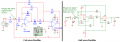
I'd like to make a Hi Speed Full wave rectifier circuit. Input frequency up to 200KHZ sinwave. About my circuit Please the Attach File. But this
circuit can't rectified over 10KHZ. if the signal is over 10KHZ, The output waveform turned become worse.

How do I improve my circuit? I wish It works well up to 200KHZ.

Many thanks
Regards

PSIR
 

Attachments

nomurphy

Joined Aug 8, 2005
567
The setup of U1A looks a bit off to me, and U1B should be a low-pass filter. Try looking at the attached for some ideas, and if using a split supply then the "ref" points can be ground.
 

Attachments

Caveman

Joined Apr 15, 2008
471
The setup of U1A looks a bit off to me, and U1B should be a low-pass filter. Try looking at the attached for some ideas, and if using a split supply then the "ref" points can be ground.
Now, why exactly would he want to low pass filter the circuit? He didn't say he wanted DC, just rectification.
 

nomurphy

Joined Aug 8, 2005
567
R4 and R5 create a summing amp of U1B, I think adding original signal (R4) with recified signal (R5) is causing distortion or phase cancelling. And, what is the purpose of R3?

Layout can also be a critical issue with a 10MHz amp.

++++++++++++++++++++/

Now, why exactly would he want to low pass filter the circuit? He didn't say he wanted DC, just rectification.
I guess I'm just being presumptuous.
 

Audioguru

Joined Dec 20, 2007
11,248
The circuit is a standard active full-wave rectifier. The values of the resistors are so high that stray capacitance combines with them to limit the high frequency response to only 10kHz. But the opamps are low power and cannot drive resistors that are low value. Try reducing the 100k and 200k resistor values to one-tenth.

Are you using these fast but low power opamps or are you using very slow opamps that is 40 years old (like the lousy old 741 opamp)?

Did you make the circuit on a breadboard that has very high capacitance between wires?
Try using a small pcb instead.
 

nomurphy

Joined Aug 8, 2005
567
The circuit I provided is simpler and works with the filter changed to a buffer amp (see attached "active_rect").

When I simulated his original schematic as given it looked like crap. By changing the connection of R4 to the other side of R2, it works (see attached "active-rect_mod") and looks very similar to mine. Input signals are 500mVpk @ 100KHz.

These are half-wave, not full-wave rectifiers.

The file "active-rect2" is a positive going, in-phase, version.

The file "active-rect_mod2" is the original with R3 and R4 removed ...look familiar? This one is at 300KHz input.
 

Attachments

scubasteve_911

Joined Dec 27, 2007
1,203
Use high-speed schottky diodes along with high speed opamps. Typically, the maximum frequency of operation, provided everything else is good, will be around 1/Ft of the opamp. As Audioguru stated, lowering your resistor values is critical for high speed operation.

Steve
 

Audioguru

Joined Dec 20, 2007
11,248
Hi NoMurphy,
Your copy of his circuit has a serious error that makes yours a half-wave rectifier but his is a full-wave rectifier.

Sure the opamp and diodes are fast. But the stray and parts capacitance against the extremely high resistor values rolls off the high frequencies.
 

Attachments

nomurphy

Joined Aug 8, 2005
567
Simulation has nothing to do with stray capacitance or layout. The circuit output looked like crap, which I've determined wasn't helped by positive offset in my setting of the source voltage.

Your copy of his circuit has a serious error that makes yours a half-wave rectifier but his is a full-wave rectifier.
It's not a "serious error" but a recognition that his method wasn't working, and by eliminating his R3/R4 it was now in the same design state as the half-wave. Note my following earlier statement when I realized my re-connection of his R4 wasn't doing anything:

The file "active-rect_mod2" is the original with R3 and R4 removed ...look familiar? This one is at 300KHz input.
Now, I've re-simulated his circuit using the LM6132 with an input of 1Vpk @ 100KHz & 300KHz, see atttached.

Notice there are issues, including phase induced distortion. It is really bad at 300KHz (strangely, it looks a bit better in the PDF than on the PC screen). I believe this distortion at higher frequencies is caused by sufficient phase shift at the summing point of his R4/R5 to throw things out of whack (sans any layout issues).

The half-wave doesn't try to sum the input with the rectified output, so it operates better at higher frequencies.

Most amplifiers of this caliber require guard-banding of the inputs, and from my second post:
Layout can also be a critical issue with a 10MHz amp.
 

Attachments

Audioguru

Joined Dec 20, 2007
11,248
Hi NoMurphy,
Please sim the original circuit with 10k and 20k resistors replacing the 100k and 200k resistors and it will work much better at high frequencies.
Then please try it with 1k and 2k resistors.
 

Thread Starter

PSIR

Joined Apr 23, 2008
29
Dear nomurphy:

I'm interested in your circuit(Active-rect1.pdf).
It looks like a single supply circuit, Doesn't it?

I usually used split supply for OPA applications. If I use split supply whether the reference power doesn't need and "ref" points can be ground?

Finally, What is the efficiency operation frequency of this circuit?

Thank you

PSIR
 
Top