Hello,
For my lab, I am supposed to design a voltage divider circuit. I have done a lot of searching and I can't seem to understand.
I don't even fully understand what the question is asking
Question:
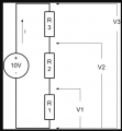
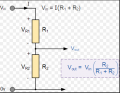
You have a 10VDC source available. Design a voltage divider circuit that has 2VDC, 5VDC, and 8VDC available
a. Draw your designs and show your calculations
Thanks
For my lab, I am supposed to design a voltage divider circuit. I have done a lot of searching and I can't seem to understand.
I don't even fully understand what the question is asking
Question:
You have a 10VDC source available. Design a voltage divider circuit that has 2VDC, 5VDC, and 8VDC available
a. Draw your designs and show your calculations
Thanks

 )
)