Thank you for your reply, Maximum current of motor is 0,34 A. my plan i will use 2 mosfet P-Channel and 2 mosfet H-Channel. but i still confuse with schematic. i will use arduino for PWM control and use optocoupler to insulated the voltage
Nope will not work you just going to burn up some parts
The IRF9630S gate voltage is 20 volts tops.
IRF630 gate voltage 20 volts tops too.
And whats going to happen any ways even if you could open the gate with 180 volt dc
the motor is not going to spin
One top IRF9630S has to be on say top left and one IRF630 bottom right
Way you have it they will shorting back a forth.
thank you for your reply.. I know how H-brigde work. because I have succesfully control of 5 vdc , 12 vdc motor. but now I need to control speed and direction rotation of motor 180vdc and still confused about right schematic to do this.
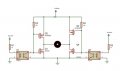
The zener diodes across the gate and source of the MOSFETs limit the maximum voltage reaching the gate. The circuit driving the two inputs will need to be able to cope with 180V though.
However, with a 180V supply, both MOSFETs will be turned on simultaneously while the input is changing and will effectively short circuit the supply during the transistions. You could use a dedicated bridge driver IC which will include circuitry to prevent this shoot-through or a circuit as below which will allow you to control the timing of the four gate signals so you can ensure that the top and bottom MOSFETs are never on at the same time.
Also note that you will need four fast diodes across each MOSFET to catch the back-emf spikes from the motor.
Read post #11 the zeners clamp the voltage so the gate it below 20 volts your parts would work if you do it like post #11
You can't pwm all 4 pins at once tho. Seeing this your first I'd use 4 pins and go with post 11
The voltage is ok you mosfet are all good for 200 volts and you don't need even a amp
But gates can't be 180 volts you'll pop them.
I'd find 4 SFH619A or some thing like them to drive the gates
The zener diodes across the gate and source of the MOSFETs limit the maximum voltage reaching the gate. The circuit driving the two inputs will need to be able to cope with 180V though.
However, with a 180V supply, both MOSFETs will be turned on simultaneously while the input is changing and will effectively short circuit the supply during the transistions. You could use a dedicated bridge driver IC which will include circuitry to prevent this shoot-through or a circuit as below which will allow you to control the timing of the four gate signals so you can ensure that the top and bottom MOSFETs are never on at the same time.
Also note that you will need four fast diodes across each MOSFET to catch the back-emf spikes from the motor.
Thank you for your reply. That optocupler can use PC817 Because i have read datasheet Viso until 5000v.but Vceo just until 80vdc ( specialy on high side )
Read post #11 the zeners clamp the voltage so the gate it below 20 volts your parts would work if you do it like post #11
You can't pwm all 4 pins at once tho. Seeing this your first I'd use 4 pins and go with post 11
The voltage is ok you mosfet are all good for 200 volts and you don't need even a amp
But gates can't be 180 volts you'll pop them.
I'd find 4 SFH619A or some thing like them to drive the gates
Thank you for your explain. So input to R6 and R3 must be connected with 1 pwm pin from MCU , R5 and R4 too connected with other pin PWM MCU. for mosfer i will use IRF630 and IRF 9630.. thats right or you have any suggestion for do this project.