How to check the problem for neon light fence tester?

Thread Starter

Tina Xiang

Joined Jul 24, 2017
4
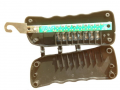
The voltage for my energizer is around 100,000V and i use a 6 light neon light fence tester to test the voltage for fence and its voltage range is 10,00V-10,000V. When i use the 6 neon light fence tester to test the voltage and all the lights are full and glitter. But when i reduced the voltage to 2KV-4KV, and all the lights are dimm, Is it normally that there will be three lights should glitter right? So is there any problem for the neon light fence tester? or the fence itself?
 
Last edited by a moderator:

Tonyr1084

Joined Sep 24, 2015
7,899
Hi Tina, and welcome to AAC.

I'm not real familiar with neon fence testers, so going on what you report, you're saying that when the fence is turned down to around 2KV to 4KV you're seeing three of the six lights light up? Well, on the assumption (and that's all this is - an assumption) that your tester is designed to light up one neon bulb at 1KV and six neon bulbs at 10KV, I'd guess that there's about 2KV per light (above 1KV). Keep in mind I said "Guess". If I read this right, three lights would be half way between 1KV and 10Kv. A 9KV spread. What I'm thinking (below) is what approximately each bulb represents as far as voltage applies.
1 bulb @ 1Kv
2 bulb @ 2.81 Kv
3 bulb @ 4.63 Kv
4 bulb @ 6.44 Kv
5 bulb @ 8.25 Kv
6 bulb @ 10.06 Kv
About 1.8125 Kv between each bulb.

This depends on the resistors used in your tester (again, assumed construction is with resistors). You used a technical term that I can't readily define: You said "Glitter". Do you mean you could barely see it lit? Or do you mean it's glowing very brightly?

Assuming your tester is working properly, it's not designed to test fences over 10 Kv. In that case I'd recommend finding one that is designed to measure that kind of voltage. I wish I could help you more, but this one is outside my realm of what I do know I do know.
 

Thread Starter

Tina Xiang

Joined Jul 24, 2017
4
Hi Tony ,Happy day and thanks for your reply and explanation.
I am sorry i wrote wrong about the voltage of my fence by last post and its voltage is also around 10KV.This neon tester has total 6 light neon lights that indicates voltage range from 1KV-10KV.First neon bulb at 1KV,second neon bulb at 2KV,third neon bulb at 4KV,forth neon bulb at 6KV, the fifth neon bulb at 8KV, last neon bulb at 10KV.So when the voltage of fence is round 10KV and to use the neon tester to test the voltage and all lights will brightly glitter at the same pace.When if turned down the voltage to around 2KV to 4KV ,and all the lights are dimm at the same pace and no light glitter.So is it normally there are three neon bulb wil glitter instead of all are dimm?Is there any problem with the fence tester itself?
 

Tonyr1084

Joined Sep 24, 2015
7,899
I don't know exactly how your tester works. Since all the lights shine at the same brightness regardless of the voltage it would appear to be malfunctioning. If there are batteries in the tester I'd suggest changing them for new batteries. It's possible low battery power can affect how the circuit responds to the test input.

Can you post a model number and any other information about your unit? Maybe we can look it up and determine how it operates. It's been many many years since I've even LIT UP a Neon bulb, let alone know how your tester is working.

Your other option is to try a different tester and see how it responds. But I would hate to tell you the one you have is "Good" or "Bad" without really knowing for sure.
 

Thread Starter

Tina Xiang

Joined Jul 24, 2017
4
hi Happy day Thanks for your reply.This type neon light tester doesn't need battery and the operation as following:
Step1 Apply power to the fence by tyrning on the fence energizer. Step2 Insert the bare mental grounding probe into the soil.It is attached to the voltage tester. Step3 Hang the voltage tester on the fence wire . Step4 Observe the voltage level indicated on the fence tester.
and the picture as attached and the inside review of 8 light fence tester and its inside structure is the same with 6 light and just for your reference.
upload_2017-10-4_20-52-52.pngupload_2017-10-4_20-53-16.png
 

Attachments

Dodgydave

Joined Jun 22, 2012
11,301
Looks like a series resistor chain across the supply, there a 3 resistors at the input, they might be Megaohms, with neons across the lower resistors, each resistor looks like 470K.
 

Tonyr1084

Joined Sep 24, 2015
7,899
This is outside the realm of my knowledge and experience. Since it would seem that if all the lights are glowing at the same level then there is something not working correctly. But before I make that assessment (before I call it bad) I wonder if the current in your fence has anything to do with it. If it's AC or DC, I don't know if that would make any difference. It would seem like AC or DC the lights should still react the same way, one neon lighting up at 1KV, two neon lights lighting up at 2KV (and so on).

Can you take another picture or two? Turn the board over so we can see what's on the other side. Maybe a little less light so there's no glare and we can see the board and components better. I'm wondering if there's a solder short (solder bridge) on something causing all the bulbs to see the same voltage. But at best I'm just guessing at this. I'm glad to see others joining in the conversation. There are some pretty smart guys and girls here who can help you better than I can.
 

Tonyr1084

Joined Sep 24, 2015
7,899
I've downloaded your picture and adjusted the contrast and some other features to try and get a better look at the board. But I think I'm still missing something because of glare along the top edge of the PCB. From the hook, it looks like there's a component labeled IT or T1 or I1, I just can't tell for sure. The second component looks like it's labeled D1. I'm a little more confident in that. The third looks like it could be the number 9. If we assume the numbers go from 1 to 11, then the second component might be labeled 10 and I'm just reading it upside down, and the first component on the left from the hook might just be the number 11. We're not going to know more until we know what's on the other side, whether they're diodes or resistors - or whatever they may be.

upload_2017-10-4_20-53-16.jpg
 

Thread Starter

Tina Xiang

Joined Jul 24, 2017
4
Hi Tony i am sorry maybe the picture is not so clearly and when i take a clearly inside view picture when at office
 
Top