hi.
please help!
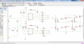
how to determine and calculate gate resistor for power Mosfet @ 6KHz frequency, VDS: 24V, ID 50A.
i put 47 ohm and it work very good. but now i want to use irfb4110 @ 6KHz, vds 30V, ID 100A. i uesd 47 ohm but there is a lot of heat dissipation and i not work good.
please how to calculate suitable resistor gate for irfb4110 with ir2111 driver?
thank you in advance
please help!
how to determine and calculate gate resistor for power Mosfet @ 6KHz frequency, VDS: 24V, ID 50A.
i put 47 ohm and it work very good. but now i want to use irfb4110 @ 6KHz, vds 30V, ID 100A. i uesd 47 ohm but there is a lot of heat dissipation and i not work good.
please how to calculate suitable resistor gate for irfb4110 with ir2111 driver?
thank you in advance