Hi. Thanks in advance for any help. This is my first post on this excellent site.
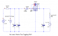
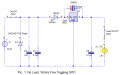
My circuit gets triggered unexpectedly, and definitely in conjunction with solenoids, compressors and/or heating elements energizing in other equipment plugged into the same outlet. Otherwise, the circuit works exactly as desired on almost all other AC circuits I’ve tried it on. I have tried to resolve this by filtering immediately across the 12v DC power supply, using a SA12AG TVS Diode, plus a 1uF cap and a .1uF cap. This has helped, but not eliminated the unwanted triggers. There are actually 2 timers in use; a 556, where the output of one of the 555’s controls the Reset pin on the other. I have attached a simulator image of the circuit, in its powered-on-and-ready state, and another one where it is being called on to pump water. My simulator doesn't have Hall sensors, so I'm just using SPST switches.


The circuit design is to control a 12v water pump and 12v solenoid water valve for a period of time. The water goes into a reservoir and then drains down through a water-sculpture. A sensor in the reservoir triggers the timer to pump the water back up again. Here are some explanations to help answer questions about the circuit design:
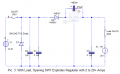
1. 12 volts is used for the water pump and solenoid valve. This comes from a 2-amp wall wart, which provides more than enough current at full load. All other circuitry is 5 volts, from a 7805 voltage regulator positioned immediately after the TVS diode and 2 filter caps. An additional .1uF filter cap is used immediately on the regulator’s output. The regulator is used to ensure that the 556 input remains steady regardless of the motor and solenoid. There are also more filter caps on the 556, as per suggestions I found here on this site.
2. The purpose of the 2nd 555 (Timer 2) is to power the pump and solenoid for a period of time; about 1 minute. It is triggered by an omnidirectional, non-latching Hall Effect sensor pulling the Trigger (pin 8) low. Its Reset pin (10) goes high on the output from Timer 1. The output pin enables an IRF530 MOSFET that provides ground to the pump and solenoid; water flows.
3. The purpose of the 1st 555 (Timer 1) is to enable Timer 2 for the same 1 minute (plus an extra 10 seconds) as a failsafe. It ensures that the pump doesn’t continue pumping water if something goes wrong, like the Hall sensor getting stuck low (it reads a floating magnet that might decide not to float). It is triggered by the low from the same Hall sensor. However, this happens via an edge-trigger to prevent a potential stuck-low Hall sensor from keeping Timer 2 triggered and pumping.
4. In addition to water being pumped by the Hall sensor reading the floating magnet, the user can press a momentary switch (Fill/Stop) to manually run or stop the pump. It engages a separate RC timing circuit, having a delay so short that effectively the pump turns off as soon as the Fill/Stop switch is released.
5. Because the 2 timers must work independently to accomplish the failsafe, yet be enabled simultaneously by the Fill/Stop switch, there are a few 2N3904 and 2N3906 transistors that enable or disable things. Also, there are LEDs to indicate Ready, Want Water, Adding Water and Timer 1 Enabled (failsafe). There is also a 2nd Hall sensor that stays low as long as the water tank’s cover is properly in place, or causes the lighting of a Cover Off LED and disabling Timer 1 and the Ready light if the cover is not in place.
Hopefully, that’s enough description to help make sense of the attached circuit diagram. I’m sure the pros know of much better ways to accomplish all of this, but it’s been about 30 years since I had any electronics training and so it’s plainly old school. I’m very open to any and all suggestions about the overall design.
But the main reason for the post is that there are 2 problematic symptoms I need help solving:
1. Problem 1 – The “Want Water (yellow)” LED comes on, and the circuit is effectively locked up. This happens without the floating magnet causing the Hall sensor to go low. And if the magnet were to try to make the Hall sensor go low, no triggering of either timer would happen (as far as I can tell). The situation can be corrected either by power-cycling the circuit, or by pressing and releasing the Fill/Stop switch.
2. Problem 2 – The circuit starts pumping water even though the floating magnet is nowhere near the Hall sensor. I have been able to duplicate this problem, somewhat at-will, again using the shared AC circuit, by unplugging and then re-plugging the other appliances. In particular, the Keurig coffee maker often initiates this unwanted triggering immediately upon being plugged in to the same outlet as my circuit. It sounds like it has its own internal solenoid that energizes as soon as it’s plugged it, whether or not the power switch is turned on.
In a long-past job, we had to add a power conditioner (like an ONEAC) to stop point-of-sale terminal lock-up problems when there were refrigerators on the same circuit. Assuming that the problem I need to solve is power-related, I am hoping for an inexpensive and simple solution that I can incorporate into my circuit design. Or maybe an alternative would be to require that the low from the Hall sensor be longer in duration (1-2 seconds) in order to trigger the two timers?
Thanks for any and all suggestions and for your patience in reading this; I hope the lengthy description helps.
-Mark
My circuit gets triggered unexpectedly, and definitely in conjunction with solenoids, compressors and/or heating elements energizing in other equipment plugged into the same outlet. Otherwise, the circuit works exactly as desired on almost all other AC circuits I’ve tried it on. I have tried to resolve this by filtering immediately across the 12v DC power supply, using a SA12AG TVS Diode, plus a 1uF cap and a .1uF cap. This has helped, but not eliminated the unwanted triggers. There are actually 2 timers in use; a 556, where the output of one of the 555’s controls the Reset pin on the other. I have attached a simulator image of the circuit, in its powered-on-and-ready state, and another one where it is being called on to pump water. My simulator doesn't have Hall sensors, so I'm just using SPST switches.
The circuit design is to control a 12v water pump and 12v solenoid water valve for a period of time. The water goes into a reservoir and then drains down through a water-sculpture. A sensor in the reservoir triggers the timer to pump the water back up again. Here are some explanations to help answer questions about the circuit design:
1. 12 volts is used for the water pump and solenoid valve. This comes from a 2-amp wall wart, which provides more than enough current at full load. All other circuitry is 5 volts, from a 7805 voltage regulator positioned immediately after the TVS diode and 2 filter caps. An additional .1uF filter cap is used immediately on the regulator’s output. The regulator is used to ensure that the 556 input remains steady regardless of the motor and solenoid. There are also more filter caps on the 556, as per suggestions I found here on this site.
2. The purpose of the 2nd 555 (Timer 2) is to power the pump and solenoid for a period of time; about 1 minute. It is triggered by an omnidirectional, non-latching Hall Effect sensor pulling the Trigger (pin 8) low. Its Reset pin (10) goes high on the output from Timer 1. The output pin enables an IRF530 MOSFET that provides ground to the pump and solenoid; water flows.
3. The purpose of the 1st 555 (Timer 1) is to enable Timer 2 for the same 1 minute (plus an extra 10 seconds) as a failsafe. It ensures that the pump doesn’t continue pumping water if something goes wrong, like the Hall sensor getting stuck low (it reads a floating magnet that might decide not to float). It is triggered by the low from the same Hall sensor. However, this happens via an edge-trigger to prevent a potential stuck-low Hall sensor from keeping Timer 2 triggered and pumping.
4. In addition to water being pumped by the Hall sensor reading the floating magnet, the user can press a momentary switch (Fill/Stop) to manually run or stop the pump. It engages a separate RC timing circuit, having a delay so short that effectively the pump turns off as soon as the Fill/Stop switch is released.
5. Because the 2 timers must work independently to accomplish the failsafe, yet be enabled simultaneously by the Fill/Stop switch, there are a few 2N3904 and 2N3906 transistors that enable or disable things. Also, there are LEDs to indicate Ready, Want Water, Adding Water and Timer 1 Enabled (failsafe). There is also a 2nd Hall sensor that stays low as long as the water tank’s cover is properly in place, or causes the lighting of a Cover Off LED and disabling Timer 1 and the Ready light if the cover is not in place.
Hopefully, that’s enough description to help make sense of the attached circuit diagram. I’m sure the pros know of much better ways to accomplish all of this, but it’s been about 30 years since I had any electronics training and so it’s plainly old school. I’m very open to any and all suggestions about the overall design.
But the main reason for the post is that there are 2 problematic symptoms I need help solving:
1. Problem 1 – The “Want Water (yellow)” LED comes on, and the circuit is effectively locked up. This happens without the floating magnet causing the Hall sensor to go low. And if the magnet were to try to make the Hall sensor go low, no triggering of either timer would happen (as far as I can tell). The situation can be corrected either by power-cycling the circuit, or by pressing and releasing the Fill/Stop switch.
a. I cannot duplicate this intermittent problem at-will. However, it happens only when my circuit is plugged into an outlet that is on a circuit shared with other appliances: toaster oven, coffee maker and possibly the hot/cold office water cooler. I have not yet had a chance to try and isolate which one(s) might be the culprit, but regardless, my circuit needs to be able to handle this, if in fact the problem is electrical noise/transients/etc.
2. Problem 2 – The circuit starts pumping water even though the floating magnet is nowhere near the Hall sensor. I have been able to duplicate this problem, somewhat at-will, again using the shared AC circuit, by unplugging and then re-plugging the other appliances. In particular, the Keurig coffee maker often initiates this unwanted triggering immediately upon being plugged in to the same outlet as my circuit. It sounds like it has its own internal solenoid that energizes as soon as it’s plugged it, whether or not the power switch is turned on.
In a long-past job, we had to add a power conditioner (like an ONEAC) to stop point-of-sale terminal lock-up problems when there were refrigerators on the same circuit. Assuming that the problem I need to solve is power-related, I am hoping for an inexpensive and simple solution that I can incorporate into my circuit design. Or maybe an alternative would be to require that the low from the Hall sensor be longer in duration (1-2 seconds) in order to trigger the two timers?
Thanks for any and all suggestions and for your patience in reading this; I hope the lengthy description helps.
-Mark