How can I increase the bandwidth of my Vackar oscillator?

Thread Starter

numberdude

Joined Dec 29, 2010
31
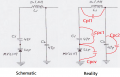
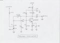
I breadboarded a low power Vackar oscillator for FM frequencies from 88MHz to 108Mhz. It is voltage tuned using an MV2107 varactor. It works pretty good, but only tunes from 88.3MHz to 103.9MHz (no antenna attached). I got this far only after much fiddling and experimenting with the caps, and not really knowing enough about what I was doing. The amplitude did vary over the tuning frequency, but not too bad I think. At 88.3MHz, output was 87mv RMS. At 103.9MHz. it was 139mv RMS. What should I change to widen the bandwidth? My circuit is attached .
 

Attachments

panic mode

Joined Oct 10, 2011
2,914
varicap diode has large capacitance at low voltage and small capacitance at higher voltage. this one is rated for 25V (absolute max 30V). by increasing voltage and reducing diode capacitance resonant frequency will increase.
the other option is to change component value of other parts in the LC circuit.
 

Thread Starter

numberdude

Joined Dec 29, 2010
31
Thanks for that suggestion. Right now I am feeding the varactor up to 18 volts. I thought of increasing the voltage to 27 volts, by using a third 9v battery, but I'd prefer to keep it to two 9v batteries if possible. I'm not sure which caps to change. I've already tried a zillion combinations. Maybe a lower capacitance varactor?
 

Janis59

Joined Aug 21, 2017
1,863
For my understanding the Vačkar circuit is well stable in the frequency what is determined not only by LC but also many other elements. Thus, You may rather easily change the LC, but the excellent frequency stability as well the brilliant phase noise will suffer. If that both are not so much important, then just decreasing the L1 would be the most simplest to do solution.
 

sparky 1

Joined Nov 3, 2018
794
There are some elaborate methods that have been contrived in contending with compromise between sensitivity and selectivity.
When tuning in a station you may want to sweep but in optimizing reception you may want a very fine adjustment.
The SDR visual touch screen has been popular. Transistor radios with a polycon variable capacitor was another.
 
Last edited:

Thread Starter

numberdude

Joined Dec 29, 2010
31
If you are basing the tuning voltage on the battery voltage, I foresee a bit of a problem as the battery depletes.
If the battery voltage drops gradually wouldn't that mean the frequency would change gradually? I can live with that as long as it's not too much or too fast. The tuning pot would just need a different setting to get the same voltage. Unless I'm missing something, which is quite possible.
 

Thread Starter

numberdude

Joined Dec 29, 2010
31
For my understanding the Vačkar circuit is well stable in the frequency what is determined not only by LC but also many other elements. Thus, You may rather easily change the LC, but the excellent frequency stability as well the brilliant phase noise will suffer. If that both are not so much important, then just decreasing the L1 would be the most simplest to do solution.
Thanks. I'm going to try that by stretching the coil a little.
 

Thread Starter

numberdude

Joined Dec 29, 2010
31
Thanks. I'm going to try that by stretching the coil a little.
Yes, decreasing L1 worked, sort of. I stretched the coil a little at a time, then checked the frequency response. It shifted the range up, but the width (bandwidth) stayed about the same. The mv2107 that I'm using only goes down to around 10pf at 16 volts. Someone suggested going up to 27 volts to decrease total capacitance, and I think that would work but then I have to use three 9 volt batteries. I'd like to keep it to two batteries if possible by messing with the capacitor values. I have to look at your circuit and do some more experimenting. That's a very intriguing wide band circuit!
 

panic mode

Joined Oct 10, 2011
2,914
If the battery voltage drops gradually wouldn't that mean the frequency would change gradually? I can live with that as long as it's not too much or too fast. The tuning pot would just need a different setting to get the same voltage. Unless I'm missing something, which is quite possible.
it will be slow....
 

Thread Starter

numberdude

Joined Dec 29, 2010
31
Yes, decreasing L1 worked, sort of. I stretched the coil a little at a time, then checked the frequency response. It shifted the range up, but the width (bandwidth) stayed about the same. The mv2107 that I'm using only goes down to around 10pf at 16 volts. Someone suggested going up to 27 volts to decrease total capacitance, and I think that would work but then I have to use three 9 volt batteries. I'd like to keep it to two batteries if possible by messing with the capacitor values. I have to look at your circuit and do some more experimenting. That's a very intriguing wide band circuit!
If you are basing the tuning voltage on the battery voltage, I foresee a bit of a problem as the battery depletes.
Yes, I need a bench power supply. Batteries are for when I get it right. They go down faster than I thought.
 

Thread Starter

numberdude

Joined Dec 29, 2010
31
Yes, decreasing L1 worked, sort of. I stretched the coil a little at a time, then checked the frequency response. It shifted the range up, but the width (bandwidth) stayed about the same. The mv2107 that I'm using only goes down to around 10pf at 16 volts. Someone suggested going up to 27 volts to decrease total capacitance, and I think that would work but then I have to use three 9 volt batteries. I'd like to keep it to two batteries if possible by messing with the capacitor values. I have to look at your circuit and do some more experimenting. That's a very intriguing wide band circuit!
varicap diode has large capacitance at low voltage and small capacitance at higher voltage. this one is rated for 25V (absolute max 30V). by increasing voltage and reducing diode capacitance resonant frequency will increase.
the other option is to change component value of other parts in the LC circuit.
My circuit is similar to the one you referenced, with a few differences. Yours uses a BB109 varactor. Mine uses an MV2107. So, I ordered a few BB109 varactors. I think it'll work better because it can achieve a better range of capacitance at lower voltages than my varactor. This circuit is known for its wideband property, so I still don't know why I can't get more than about 15 MHz of bandwidth. Could be the varactor, or the crappy pot I'm using for tuning voltage. Maybe the choke needs to be bigger. You'd think with all the different combinations of capacitor values I tried, that I'd find something that greatly affects the bandwidth. Everything I tried only shifts the range up or down. I just need to widen the range a little more, about 5MHz.
 

panic mode

Joined Oct 10, 2011
2,914
ok... as you are numberdude, lets focus on some ... numbers...

LC oscillator resonant frequency is f = 1 / (2 * pi * sqrt(L * C))

2 and pi are constants. and since L is fixed, you can rewrite it as f = k0 / sqrt(C)
where k0 contains all of the constant factors that do not change so we can only focus on change in C

if the C changes in range of 4-24pF, that is a 6-fold change, so we can rewrite the equation as
C=C0*n where C0=4pF, so we get:

f = k0 / (sqrt(C0)*sqrt(n)) = k1/sqrt(n)
where n value changes in range 1...6

and value sqrt(n) changes in range 1..2.45
so if k1/2.45 = 88MHz, then k1/1 = 215.6MHz. so we got the bandwidth and then some...

the thing is that varicap diode (varactor) is not the only component of the "C".
there are other capacitors in the circuit and we need to see how the overall C value changes when diode capacitance Cv changes.

look at schematics shows that C1, C2 and varicap diode are all in series.


C1 and C2 are same value and in series so that is equivalent of a single capacitor C12 of half the value (23.5pF) which closely matches max capacitance of the varicap. so this looks good and should work perfectly...

because if we mark that as C12 and varicap capacitance as Cv
we get

C=C12*Cv/(C12+Cv)
so when Cv=4pF we get overall C = 23.5*4/(23.5+4)=3.4pF
and when Cv=24pF we get overall C=23.5*24/(23.5+24)= 11.87pF

ok... so even though Varicap capacitance range was 4-24pF (range 1..6x), overall capacitance change C is smaller, only 3.4-11.87pF which is merely C range 1-3.5x
and when we take a square root of this C value we only get range 1..1.87x
sooooo.... should we not get something like 88-164.4MHz then?

the answer is: in an ideal world yes... but in practice - not really...

the problem is that mentioned values are only capacitances of components shown in the schematics.... but there are others...
they are called parasitic capacitances. and they strongly depend on used construction methods. this is something that you have not shown but link i shared does show how this could and should be built to minimize those unwanted capacitances.

because if you are using a breadboard, it is a miracle that this even works. because they will have some 10-20pF of parasitic capacitance just between two tracks. so doing anything on breadboard that is 20-30Mhz or faster is rather challenging... not to mention 108MHz.

so your Cv is not 4-24pF any more, it is really more something like 24-44pF. so the dynamic range is dramatically reduced... it is no longer 1..6x, it is hardly 1..2x.

but that is not all... it is not only Cv that is affected... all other parts of the circuits would have them too. so net dynamic range will be even smaller, perhaps 1..1.2x or maybe 1..1.3x.

and when you take square root of those C values, you can see why your frequency range is doomed.

so... what can be done?

great care must be taken when constructing things that operate at high frequencies. construction method must be one with inherently low parasitic capacitance, all connections need to be as short as possible etc. good idea is to take a look how tuner (TV, radio, VCR) are constructed. choose varicap that will get you range you need. this may require using higher voltage because that is how you get the low capacitance and wider range.

4-24pF is only 6x the value change
3-24pF is 8x the value change. that 1pF is such a small, hardly noticeable difference... yet it makes a big impact...
2..24pF is 12x the range. tiny 2pF change doubled the range.
 

Attachments

Last edited:

Thread Starter

numberdude

Joined Dec 29, 2010
31
ok... as you are numberdude, lets focus on some ... numbers...

LC oscillator resonant frequency is f = 1 / (2 * pi * sqrt(L * C))

2 and pi are constants. and since L is fixed, you can rewrite it as f = k0 / sqrt(C)
where k0 contains all of the constant factors that do not change so we can only focus on change in C

if the C changes in range of 4-24pF, that is a 6-fold change, so we can rewrite the equation as
C=C0*n where C0=4pF, so we get:

f = k0 / (sqrt(C0)*sqrt(n)) = k1/sqrt(n)
where n value changes in range 1...6

and value sqrt(n) changes in range 1..2.45
so if k1/2.45 = 88MHz, then k1/1 = 215.6MHz. so we got the bandwidth and then some...

the thing is that varicap diode (varactor) is not the only component of the "C".
there are other capacitors in the circuit and we need to see how the overall C value changes when diode capacitance Cv changes.

look at schematics shows that C1, C2 and varicap diode are all in series.


C1 and C2 are same value and in series so that is equivalent of a single capacitor C12 of half the value (23.5pF) which closely matches max capacitance of the varicap. so this looks good and should work perfectly...

because if we mark that as C12 and varicap capacitance as Cv
we get

C=C12*Cv/(C12+Cv)
so when Cv=4pF we get overall C = 23.5*4/(23.5+4)=3.4pF
and when Cv=24pF we get overall C=23.5*24/(23.5+24)= 11.87pF

ok... so even though Varicap capacitance range was 4-24pF (range 1..6x), overall capacitance change C is smaller, only 3.4-11.87pF which is merely C range 1-3.5x
and when we take a square root of this C value we only get range 1..1.87x
sooooo.... should not we get something like 88-164.4MHz then?

the answer is: in ideal world yes but in practice... not really...

the problem is that mentioned values are only capacitances of components shown in the schematics.... but there are others...
they are called parasitic capacitances. and they strongly depend on used construction methods. this is something that you have not shown but link i shared does show how this could and should be built to minimize those unwanted capacitances.

because if you are using breadboard, it is miracle that this even works. because they will have some 10-20pF of parasitic capacitance just between two tracks. so doing anything on breadboard that is 20-30Mhz is a rather challenging... not to mention 108MHz.

so your Cv is not 4-24pF any more, it is really more something like 24-44pF. so the dynamic range is dramatically reduced... it is no longer 1..6x, it is hardly 1..2x.

but that is not all... it is not only Cv that is affected... all other parts of the circuits would have them too. so net dynamic range will be even smaller, perhaps 1..1.2x or maybe 1..1.3x.

and when you take square root of those C values, you can see why your frequency range is doomed.

so... what can be done?

great care must be taken when constructing things that operate at high frequencies. construction method must be one with inherently low parasitic capacitance, all connections need to be as short as possible etc. good idea is to take a look how tuner (TV, radio, VCR) are constructed. choose varicap that will get you range you need. this may require using higher voltage because that is how you get the low capacitance and wider range.

4-24pF is only 6x the value change
3-24pF is 8x the value change. that 1pF is such a small, hardly noticeable difference... yet it makes a big impact...
2..24pF is 12x the range. tiny 2pF change doubled the range.
Wow! You really spent time on your very informative response. Thank you! Yes, I am Numberdude because I was a math teacher. So I appreciate your clear mathematical explanation. It made perfect sense. I always knew to watch out for parasitics, but I never did. Looks like a breadboard is a bad idea for high RF. I learned a lot from your effort. I will rebuild my circuit on a piece of perfboard and follow your layout. My breadboard layout is a bit of a mess. I've seen some RF circuits built on a copper ground plane. Do you think that would be better than perfboard? Again, thank you for your detailed explanation. I was getting very frustrated and this is "news I can use" and I appreciate it greatly. I'll let you know how I make out.
 

panic mode

Joined Oct 10, 2011
2,914
perfboard or just about any PCB based construction will be much better than breadboard. also keep in mind that leads of all parts should be kept short. decades ago when i was toying with FM transmitters, most of the PCBs i was using at that time were single sided PCBs with 15-20 parts on a board about an inch long. soldered connections are stable and leads can be short (impossible on a breadboard).
 

panic mode

Joined Oct 10, 2011
2,914
this is how breadboard looks inside... note the large area of the individual metal contacts that are arranged in parallel with the next one. two of those will have much higher capacitance than two wires or PCB tracks that are same distance from each other:
 
Top