Facebook
 Google
 GitHub
 Linkedin
Thanks SO much for your patience and understanding. Being the jack-leg “technician” that I’ve been for many years I’ve had good luck with fixing many things. And that sense of accomplishment—you just can’t beat it. But sadly I’m realizing the depth at how things have changed so much and even farther above my head. Yes, I’ll be the first to say “I shouldn’t be messing with things that can be really dangerous, without the training…” but you can’t change a hard head. I do, however, try my best to take precautions—I HATE getting zapped! It gets my attention and HOW! But I keep doing it. It’s just in my 65 YO DNA.Hi,
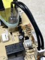
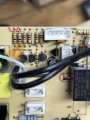
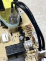
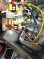
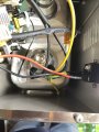
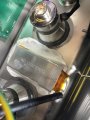
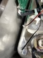
Earlier, I mentioned a thermal fuse, It's cable tied to a transformer. Two thick black cables with a plug on the end of it.
A simple check, unplug it and test for continuity . e.g. it should show a short circuit if it's good.
I appreciate all this stuff is blowing your mind. Anything you don't understand, just ask the forum
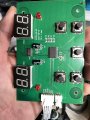
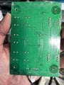
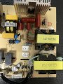
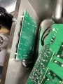
It’s very frustrating—I take this board out and look it over, hoping for something obvious. (like in other things) But when it’s not then I realize I really need to understand what’s going on within the boards, what the parts do and how they contribute to the end functions. That’s fascinating too. And it looks like it should be so simple to figure out what’s not happening. LOL I know better but I can’t help thinking it. I believe it’s because I’ve witnessed guys that make it look so easy to track down problems. I realize there’s years of training/experience behind that and here I have been for many years hoping I could stumble upon the “secrets” and “shortcuts” that would let me sort-of compete… I know better but a fellow can dream, huh? Luckily, guys here and other types of forums have been very helpful and non-judgmental, and with that have given me much success. Most times, it’s as if they (y’all) love to teach your talents and enjoy seeing others win in their efforts. Lord knows it seems that we are seeing a decline in folks that can fix things and that’s sad…(sorry about the long-winded response… I get a little passionate )
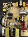
Hopefully later tonight I’ll dig back into that board and into that specific area you mentioned. And I’ll look those things up to learn a little more.
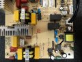
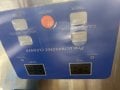
Another side note: would it be a terrible idea to suggest an occasional board be posted, with and without schematics, and then you guys might have some time to give a synopsis of what the board should do, how it goes about it, maybe ID the parts, and possibly using your skills detail how the signals move through the board to get their desired result? That’s a tall order I know. On this particular board of mine, I figure 1. It takes normal house current in, then changes it in some places for different functions, (rectifiers, transformers) converts to some signal that feeds the transducers that sort-of vibrate the bowl of fluid, supplies power to turn on a heater for the fluid, etc. Sadly, I’m just too old to go “back to school” and hit the books—too many other issues to deal with around me, and my mind can’t settle down long enough for that kind of learning.
Again, many thanks