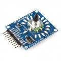
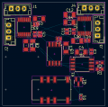
Help with PCB design for rotary switch on vintage tube preamplifier

Thread Starter

neevo

Joined May 8, 2024
7
Hello everyone! Over the past 5 years I have been restoring a very worse for wear McIntosh C20 Tube Preamplifier. The build is complete and looking beautiful (I documented it fully on a major audio forum) and along the way I build some replacement parts for it, as they are mostly unavailable given the age of the machine (1959-1963). I am currently designing and building a replacement volume potentiometer which has an integrated power switch as these are known to go bad on McIntosh's and whilst replacements are available on the auction site (I bought one and its been great), many people complain about the quality of them. A wonderful option is available from Gold Point, but it requires modification to the C20 which I am trying to avoid with mine.

Here is my plan: 4 audio PCB's and a power PCB at the rear

C20 Pot Covered.png

C20 Pot Nude.png

This is my design for the audio PCB. A 37 segment stepped attenuator that will use a potentiometer wiper to make the selections:
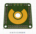
Audio PCB.png

I am really comfortable with the design of the audio PCB's, but I would really like some support on the PCB for the power switch as its much more dangerous if I get it wrong, plus I cannot risk damaging my C20 if I happen to mess it up. I am one of those people who knows enough to be dangerous, so I would prefer to progress with significant caution.

I am effectively trying to replace a rotary switch which takes up a lot of travel of the volume pot (25%) and turn it in to a 7.5 degree switch. My plan was to try and use a triac to do the switching and a voltage divider circuit to drop down the voltage and current to allow me to use the same type of potentiometer wiper/track circuitry to activate the gate. However because its driving an inductive load, I am now also considering adding in a snubber circuit for safety on the triac side too.
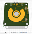
Power PCB.png

I used some simulation software to see if the voltage and current would be ok to put on a potentiometer wiper track and got something so low, that it appeared fine. But I am keen to triple check my thinking here is correct. Plus I am keen to understand if my plans to put all of this on a PCB (40mm x 40mm) will work for the application (eg heat from the triac, ensuring I can manage electrical noise in a preamp).

1. Can I use a potentiometer wiper and hard gold track to activate a triac gate

C20 is on 117v and uses 35w of power
I was reading the voltage and current on the switch as:

Switch voltage: 740 mv
Switch current: 70 uA
Gate voltage: 11 mv
Gate current: 62 uA

Do I have this correct? This would suggest to me that my concept to use a potentiometer wiper to activate the gate will work.

Voltage divider circuit.png

I am trying to package everything together on a PCB as tightly as I can. What do I need to consider in the PCB design to ensure it will work reliably, safety and effectively? Currently I have designed thicker than required tracks for all connections as a safety margin and I am finalising the new PBC design at the moment that I would love to get some feedback on too, to make sure I have not made any fatal errors.
 

Ian0

Joined Aug 7, 2020
10,289
A few things to consider:
1. Do your local standards require a SAFETY ISOLATING switch? A triac does not qualify as such. It means that the rest of the circuit must be considered as live, even when the power is off.
2. You need to observe creepage and clearance distances between any parts connected to your triac, and earth, and any other metal parts, and any earthed circuirty. The distances are probably about 3mm, depending on local regulations.
3. A power triac is likely to need a gate current of 50mA, and will have a gate voltage of about 1V.
4. If the triac fails, it will fail short, so the rest of the circuitry will remain live.
5. How does the switch behave if the wiper is right on the edge of the conducting zone? What stops the triac conducting half-wave and destroying the transformer?
 

Thread Starter

neevo

Joined May 8, 2024
7
Hmmmm, these are all great questions. Focussing on the 1 that concerns me the most. If the triac fails, it will fail open (which then also has an impact on 1). Not something I had considered but definitely a worry.

Are there any other options that would be a better suited alternative? The reason for me exploring an electrical solution to switching the power was because I cannot find any suitable switches to incorporate in to my design.

The only reasonable option right now would be a mechanical micro switch and a cam on the rear to activate the arm.
 

Ian0

Joined Aug 7, 2020
10,289
If your local regulations require an isolating switch, it could be on the back, and your electronic switch can switch between “on” and “standby”, but regulations usually require an indicator to show that it is on standby, and it must use no more than 0.5W.

You could add a tiny power supply (link switch type of thing) to give an isolated 12V supply, then use that to switch an opto triac away from the volume control.
I would also think about interference from a mains circuit so close to the input of the amplifier.

I like your volume control, Is it adapted From an existing switch or is the entire thing home made?
 

Thread Starter

neevo

Joined May 8, 2024
7
I had thought about an octocoupler, but that doesn’t sound like it really solves the triac failing issue does it, just makes the gate trigger a bit safer (I assume).

Maybe I need to look further in to mechanical options or find a need for an external switch as a backup. I know the Goldpoint version just does the volume and they require the unit to be switched externally. In fact I switch mine from my power amp anyway and bypass the switch altogether.

Looking at my assumptions on the voltage and current on the switch (or pot), have I calculated those correctly?

Re the audio PCB, yes that’s my own design but it’s not that unique as they exist already, I just took the concept and made my own PCB using Fusion 360 Electronics (which has been a nightmare to learn).
 

Thread Starter

neevo

Joined May 8, 2024
7
Would a relay be a better option to replace the triac? Would that solve the failure issue as if it fails it would fail open? Plus if it had a delay built in, would that also solve the issue with the potentiometer wiper initially triggering the relay and causing issues with the power to the transformer?
 

Sensacell

Joined Jun 19, 2012
3,509
Avoid the triac concept- very tricky and not much value in terms of function/reliability
I second the cam and microswitch idea- simple, safe, reliable.
 

Thread Starter

neevo

Joined May 8, 2024
7
The only thing that bugs me with the micro switch is losing so much of the rotation of the volume pot activating the switch. My eBay switch takes about 25% of the rotation, so ideally I could do that in 15 or so degrees, but I’ll have to play around with it.

Luckily I have a machine shop and 3D printer. So I can test a few concepts.
 

crutschow

Joined Mar 14, 2008
34,912
Unless you are concerned about restoring it to the exact original operation, I would eliminate the switch, as it is not used in most normal installations anyway.
But if you must, then adding a mechanical relay would be simple, fail-safe, and avoid running mains voltages to the control.
 

Irving

Joined Jan 30, 2016
4,088
Welcome to AAC

The only thing that bugs me with the micro switch is losing so much of the rotation of the volume pot activating the switch. My eBay switch takes about 25% of the rotation, so ideally I could do that in 15 or so degrees, but I’ll have to play around with it.

Luckily I have a machine shop and 3D printer. So I can test a few concepts.
Magnet and reed switch?

Here's a more sophisticated solution...
I recently did a noise-free digital pot that uses a diametric magnet and a AS5600 rotary encoder pcb ($9 and $6 respectively on eBay), an ATTiny85 MCU and a Dallas DS1882 dual-channel 63 step noise-free digital pot. Here I've added another DS1882 to give two more channels and a relay to switch the main power on. All you need to do is provide a mechanical detent for the off position of the shaft.

1715181618212.png
 

Thread Starter

neevo

Joined May 8, 2024
7
@Irving do you have any pics of the finished item? I think I might struggle to get it all within the 40mm x 40mm footprint, but I’m intrigued by the concept.

I’m not sure I have my head around how it works just yet either but will spend a bit more time with the schematic to understand it a bit more.
 

Irving

Joined Jan 30, 2016
4,088
@Irving do you have any pics of the finished item? I think I might struggle to get it all within the 40mm x 40mm footprint, but I’m intrigued by the concept.
Sorry, no. I didn't build it myself, it was done by a colleague. I might have the PCB layout to hand when I get back to my office, though that's only 2 channels not 4, and no relay. But no reason it can't be on 2 PCB

I’m not sure I have my head around how it works just yet either but will spend a bit more time with the schematic to understand it a bit more.
Basically the AS5600 gives a 12-bit value (0 - 4095) dependant on the orientation of the magnetic field above it. The ATtiny85 software reads that value every 10mS, maps it onto the desired 65 wiper positions, sets the relay on or off and writes the desired attenuation to all DS1882 channels. Say you want 0 to be the off position, 1 to be on, but muted and 2 - 64 to be -62 thru 0dB attenuation. over a mechanically constrained 288 degree rotation, ie each step ~4.5deg, then you could do something like this:
Code:
#define MUTE 63
#define MAXROT 3276 // eq 288/360 *4096 - 1
loop(){
  int rawpos = readFromAS5600();
  int pos = map(rawpos, 0, MAXROT, 0, 64);  //pos now 0 - 64

  if(pos==0){
 //0 = off
    writeToDS1882s(MUTE); //mute audio
    digitalWrite(relay, LOW);
  } else if(pos == 1){
//1 = on but muted
     writeToDS1882s(MUTE); //mute audio
     digitalWrite(relay, HIGH);
     delay(250); // wait for power to come up
  } else  {
     writeToDS1882s(64-pos); //set level of audio
  }
  delay(10);
} // end loop
which can be refined for soft resume to default levels, etc.


Here's another idea. Use a standard rotary encoder with push switch (push on, push off) to set the level sent to the DS1882s, but show the level set with a 270deg array (ring) of 32 x 2mm square addressable LEDs - something like this, but more refined:
th-1861580254.jpeg
 

Irving

Joined Jan 30, 2016
4,088
I might have the PCB layout to hand when I get back to my office, though that's only 2 channels not 4, and no relay. But no reason it can't be on 2 PCB
I didn't, but 10min with KiCAD shows it would probably fit on a single 40mm x 40mm PCB, though will need care to avoid mains hum from relay on audio feeds

1715277372962.png
 

MisterBill2

Joined Jan 23, 2018
19,593
REALLY! You will not be happy with the buzz if you use a triac for power control. And you certainly do not want mains power voltages near low level audio circuits . Also, a small wiper and copper trac will not last long switching a power amplifier. The very best choice will be a push pull, or push push alternate action switch operated by the shaft moving in and out. THAT is fairly common. The actual mains power control can be with a relay contact, with a very small transformer/rectifier/filter so the switch only controls the relay coil. You could use AC if the switch is far enough away from the audio signals.
I do offer a concern about the volume control, which is that it does not look to me like a potentiometer arrangement. It does not appear to be a voltage divider like most volume controls.
 

Thread Starter

neevo

Joined May 8, 2024
7
I’m going to play around with some options to see if I can get a cam and micro switch to work. This mechanical arrangement is something I am very comfortable with, so no where near as concerned vs the PCB. Plus it’s very consistent with how the original switch worked. Hopefully I can get the cam angles to work nicely with the 7.5 degree notches on the ball detect in the stepped attenuator.

@MisterBill2 what are your concerns with the stepped attenuator? The design should work as per a carbon track pot but using resistors in series as the increasing resistive load. This is certainly the most basic pot as it stacks up the resistors vs something like a ladder stepped attenuator.
 

MisterBill2

Joined Jan 23, 2018
19,593
It is entirely possible that I missed seeing come PCB connections in the photo in post #1. If the connections duplicate the common attenuator circuit then there is no issue at all. That was not obvious as I saw the photo on my computer screen at the time. The thin black traces, possibly on the reverse side of the PCB are difficult for me to see.
I was not asserting an error, only that I did not see what should be present.
 
Top