help on powersupply

Thread Starter

popto

Joined May 1, 2009
44
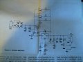
I built a variable power supply from a kit and it worked fine. I accidentally short circuited it for a while and if broke. I learned from the mistake and bought some insulated alligator clips so that the same thing won't happen again. But the problem is that my power supply is still broken. At first after it broke, it was putting out 34 volts and wouldn't change (it was supposed to work from 1.24-24 volts). Then I changed the two main transistors and another smaller one because they had all been really hot. That helped but now it is putting out 7 volts and changes a little bit when I turn the knobs but not much. What should I change next or what is the problem? Do I just have to do trial and error until I get the right part? I am a beginner and have know Idea what to do.:confused:
 

Attachments

Last edited:

bertus

Joined Apr 5, 2008
22,278
Hello,

Do you have the schematic of the powersupply?
This will give more information than the pictures you posted.

Greetings,
Bertus
 

SgtWookie

Joined Jul 17, 2007
22,230
Look to the right of C3 on the board; it looks like a resistor has burned up. Hard to say which resistor it is from the photo, it may be R8 or R7.
 

Thread Starter

popto

Joined May 1, 2009
44
it is definitely burned out. I will replace that and see if it works. you can see the resistor better in the picture than just looking at it because of the flash.

thanks.
 

Wendy

Joined Mar 24, 2008
23,429
It is also entirely probable that T2, T3 or both have blown out and shorted.

You'll need to do a meter check of the transistors, as a minimum. If you have a transistor tester I'd use it.

Looking at the schematic I can't help noticing no fuse, which is a major design flaw. It is easy enough to fix however, you can get chassis mounted fuse holders and add it as an aftermarket item.
 

Thread Starter

popto

Joined May 1, 2009
44
I had already replaced the T2 and T3. I replaced the R8 resistor and the whole thing works exempt that now it doesn't reach it's full 24 volts but maxes out at 20.1 volts. Why is that? The Italian friend who gave me the kit (it was an old one that he had never built) told me to put a 1 amp fuse between the 220 wire and the transformer and then a 3 amp fuse between the transformer and the circuit. Are those the right fuses or do I need to put them in different places?

thanks.
 

Wendy

Joined Mar 24, 2008
23,429
The fuses sound good.

Did you use exact replacements on the transistors?

Check the input voltage under full load to board, it is possible the transformer may have been damaged, or the rectifiers.

Or T1.

***********************

A question. Do they have Radio Shack stores in Italy?

Your english is excellent. I have a very scaled down version of your power supply I built 30 years ago, that is still giving good service. It uses a modified 5V power supply board Radio Shack used to make that also used a LM317 (TO3 case style). You keep taking care of this unit and it's service could be easily as long.
 
Last edited:

SgtWookie

Joined Jul 17, 2007
22,230
The schematic actually specifies 1.2v to 20v.

If you really want to increase the maximum output voltage, you could decrease the resistance of R8 somewhat. This will cause more current to flow through the P1/P2/R7 network, resulting in a corresponding increase in voltage at the ADJ terminal; hence the output voltage of U1 will increase (I'm assuming it's an LM317T at the moment; if it's something else, tell us.)

The value of R8 was not specified on the schematic diagram. What value did you use for it, what is the specified R8 value, and what are the values of R7, P1 and P2?
 

Thread Starter

popto

Joined May 1, 2009
44
They don't have Radio shack but they have small electronic components and stuff stores. I went to the equivalent of radio shack here in Italy and showed them the T1, T2, T3, and they got me the exact same ones. I tested the transformer and it is normal. the diodes smelled funny right after I messed the whole thing up but I assumed that I was just smelling the transistors. Could the diodes be causing the slight lack of voltage and if so should I change them? I am American, my parents are missionaries, I have good English because of my mom.

thanks for the help
 

Thread Starter

popto

Joined May 1, 2009
44
The power supply used to go up to 24 and I was just wondering why it is 20 now. R8 used to be 120Ω and I replaced it with another 120Ω resistor. R7 is 2,7 kΩ. P1 is 1 kΩ. P2 is 4,7 kΩ. U1 is LM317 without a (T), I don't know if that makes a difference.
 

SgtWookie

Joined Jul 17, 2007
22,230
Well, you were measuring 34v on the output when it was malfunctioning.

If you're using 24VAC on the input, that's what I'd expect to see on the output of the rectifier bridge with no load current.

Does the output voltage change significantly when you connect a load? If it does, I'd suspect the bridge rectifiers.
 

Thread Starter

popto

Joined May 1, 2009
44
I tested the power supply by running a 9volt motor and when I connected it the voltmeter didn't dip at all. Oh and I messed up when I said that I had replaced T1, T2, and T3. I didn't replace T1, I replaced U1. Sorry about that.
 

SgtWookie

Joined Jul 17, 2007
22,230
The power supply used to go up to 24 and I was just wondering why it is 20 now. R8 used to be 120Ω and I replaced it with another 120Ω resistor.

R7 is 2,7 kΩ. P1 is 1 kΩ. P2 is 4,7 kΩ.
OK. The series/parallel network of R7, P1 and P2 calculates out to 1.83k Ohms; in the LM317 datasheet this is represented as R2.
R1 (your R8) is normally specified as 120 Ohms. With a Vref (voltage between the OUT and ADJ terminals) that's typically 1.25v, this gives a nominal 10.416mA current through R1.

The 10.416mA gets an additional 20uA to 100uA added from the ADJ terminal, that's nominally 50uA - so we'll go with 10.466mA for the calculation.
10.466mA x 1.83k Ohms = 19.154V at the ADJ pin, plus 1.25v for Vref = 20.404v. You're nearly "spot on" with the specifications given.

If you really want it to go up to 24v, replace R8 with a 100 Ohm resistor. This will give a 12.5mA current flow that the R7/P1/P2 network will sink. Adding the nominal 50uA from the ADJ pin gives 12.55mA to flow through the 1.83k R7/P1/P2 network.
12.55mA x 1.83k = 22.9665v; add the Vref of 1.25v = 24.2165V.

Make sense to you?

U1 is LM317 without a (T), I don't know if that makes a difference.
OK. The "T" suffix is used when ordering the regulator to specify the TO-220 package, which is what it appears that you have.
 
Last edited:

SgtWookie

Joined Jul 17, 2007
22,230
I tested the power supply by running a 9volt motor and when I connected it the voltmeter didn't dip at all. Oh and I messed up when I said that I had replaced T1, T2, and T3. I didn't replace T1, I replaced U1. Sorry about that.
OK, that makes perfect sense then.

Your old U1 may have had a higher Vref than your new U1. The Vref is nominally 1.25v, but can be anywhere from 1.2v to 1.3v and still be within specifications.

If you measure the voltage from U1's ADJ pin to the OUT pin, you'll see just about 1.25v with this new regulator. The old one probably had a somewhat higher Vref, and/or the old R8 was probably closer to 100 Ohms.
 

Thread Starter

popto

Joined May 1, 2009
44
Thank you very much. I am not really trying to get a higher voltage on the output, I was just wondering why it had gone down to 20 volts. I have a question, will the 3 amp fuse between the transformer and the board blow if there is a prolonged short circuit, and if it will, will it blow before other stuff does?

On some papers that came with the kit it shows another circuit board that is supposed to protect from short circuits and disconnects the power when you make a short circuit, it has a push button to reset it. I can't buy that specific piece because the whole kit is about 15 years old as far as I can tell, and they don't make it anymore.
 

SgtWookie

Joined Jul 17, 2007
22,230
Thank you very much. I am not really trying to get a higher voltage on the output, I was just wondering why it had gone down to 20 volts.
It's common for "old stock" components to drift in their values after sitting in storage for years. I have some resistors that were made in the late 1960's that were originally 1% tolerance, but have radically changed from their marked values.

I have a question, will the 3 amp fuse between the transformer and the board blow if there is a prolonged short circuit, and if it will, will it blow before other stuff does?
The fuse should be what the supply's current rating is. If you have doubts, use a fuse of lower current rating.

On some papers that came with the kit it shows another circuit board that is supposed to protect from short circuits and disconnects the power when you make a short circuit, it has a push button to reset it. I can't buy that specific piece because the whole kit is about 15 years old as far as I can tell, and they don't make it anymore.
You might see if you can find a 2a or 3a automotive-type circuit breaker, if you want to spend the money. Fuses are inexpensive and effective.
 
Top