Help me understand the use of zener diodes a bit more.

Thread Starter

robotDR

Joined Mar 17, 2020
90
Hello All
Thank you for taking a look.
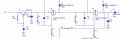
I thought zener diodes only clamped voltage on their cathode side, to their breakdown voltage. In the schematic below, why is the anode side clamped to 12 volts to make the gate of the mosfets 24-12V = 12V (-12V gate to source)? (D4 or D5).
1634071874387.png
Thank you for your time!
 

Attachments

Papabravo

Joined Feb 24, 2006
21,225
With the Anode at GND, the Cathode will be approximately at the Zener voltage, with relatively small variations, for for a range of currents.
With the Anode at some voltage with RESPECT to GND, the Cathode will be approximately at the Zener Voltage above the Anode, with relatively small variations, for a range of currents.

Remember this: All voltage drops in a circuit are relative, and represent differences in potential between two nodes. Nowhere is it written that one of the voltages on a circuit element MUST be GND. It can literally be anything at all.
 

Thread Starter

robotDR

Joined Mar 17, 2020
90
With the Anode at GND, the Cathode will be approximately at the Zener voltage, with relatively small variations, for for a range of currents.
With the Anode at some voltage with RESPECT to GND, the Cathode will be approximately at the Zener Voltage above the Anode, with relatively small variations, for a range of currents.

Remember this: All voltage drops in a circuit are relative, and represent differences in potential between two nodes. Nowhere is it written that one of the voltages on a circuit element MUST be GND. It can literally be anything at all.
Thank you for your response.

With Q4 on, the anode of D5 is at ground through Q4. How can D5 hold the cathode at 12 volts with D6 and Q1 setting that voltage to 24V?
 

Papabravo

Joined Feb 24, 2006
21,225
Thank you for your response.

With Q4 on, the anode of D5 is at ground through Q4. How can D5 hold the cathode at 12 volts with D6 and Q1 setting that voltage to 24V?
That is not correct because R12 prevents that from happening. Any current through D5 and R12 will produce a voltage drop across R12, and the Anode of D5 will NOT be at GND, even though the Drain of Q4 might be, or close to it. This will be more than enough to turn Q3 ON.
 

AnalogKid

Joined Aug 1, 2013
11,036
I thought zener diodes only clamped voltage on their cathode side, to their breakdown voltage.
That is a common use, but not the only one.

Under normal operation with enough current, a zener diode maintains a constant reverse voltage across its junction. It doesn't know about Vcc, GND or the phase of the moon. *You* might be holding one end at a fixed potential and letting the diode clamp something at the other end, but the diode doesn't care which end is fixed and which end is clamping. If it sees a potential difference greater than its zener voltage, it tries to suck down enough current to bring its two terminals closer together in voltage.

ak
 

dcbingaman

Joined Jun 30, 2021
1,065
The zener will always clamp the voltage difference across it to the zener voltage (assuming the voltage across it exceeds the zener voltage), by pulling current. In this circuit, if you remove both zeners, the voltage from gate to source for Q2 and Q3 would be around 24V*20K/30K = 16V. With the zeners it approaches 12 volts when being turned on. The zener starts to conduct current at 12V and holds the gate to source voltage at 12V. In this case the current through the 10K resistor legs of R11 and R12 will be (24V-12V)/10K or 1.2mA. The current through R6 and R7 will be 12V/20K or 0.6mA and the other 0.6mA will flow through the zeners. R6 and R7 help reduce the current and thus the power drop for the two zeners, to 1/2 what it would be if R6 and R7 were not present.
 
Last edited:

Thread Starter

robotDR

Joined Mar 17, 2020
90
Ok I'm starting to see it now. All of your responses came together in my mind and it's clicking. Thank you very much for that.
 
Top