Help me fix this!!!

Thread Starter

Supervisor

Joined Jan 17, 2009
32
Hello all!
Hoping that the community can help me fix a small problem...
I've linked a picture with the circuit layout...
http://www.fileden.com/files/2008/9/4/2081882/Help.TIF
(.TIF is a picture file - just open with paint or something [.jpg doesn't preserve quality])

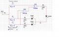
Problem is (look in picture for the labels I'm talking about) that I need to make LED1 (located by the big "1" in the picture) light up...
Thing is, the only way that it lights up is if either one of the LEDs near the big "2" get "lighted" up by completing the connection.
I do not want the connection to be complete at all, and I've tried to link up LED1 with the the end of the circuit (by ground [bottom left]) but then the LEDs by "2" will not light up at all, even if I connect the circuit...

So, how do I make the LED at "1" light up without having to complete the circuit by making the LEDs at "2" light up?

Help me!!!
 
Last edited:

mik3

Joined Feb 4, 2008
4,843
First, TTL logic family uses 5V for its logic ICs and not 12V. If you use 12V in reality the chip is gone.

Second, use a 320 ohm resistor in series with each led and connect all the resistors at the output of U3A. Also, connect the right side of LED1 to ground. Note, that a real chip can't supply the current when all the 3 leds will light the same time. Thus, you will need a transistor to buffer (increase the current capability) the output of the IC.
 

Thread Starter

Supervisor

Joined Jan 17, 2009
32
Second, use a 320 ohm resistor in series with each led and connect all the resistors at the output of U3A. Also, connect the right side of LED1 to ground. Note, that a real chip can't supply the current when all the 3 leds will light the same time. Thus, you will need a transistor to buffer (increase the current capability) the output of the IC.
:-(
I have NO idea of which transistor to use...
Waah... First year in electronics.

I do know what a transistor does, but when I tried to put one in (I just picked out of the variety), I still get around five (5) volts...

Ahhh! Help!
 

mik3

Joined Feb 4, 2008
4,843
Ok, lets start from the beginning.
What do you want to do with the circuit?
For a transistor you can use a BC108 if you are going to drive only 3 leds or a BFY51 for more leds.
 

Thread Starter

Supervisor

Joined Jan 17, 2009
32
Thank you for taking the time to help ^_^
Alright here goes...

As you can tell by the picture, the left side of the project determines whether or not there is currency in the machine or not. If yes, it activates a LED to show that there is money.

Next, the user will make an input for one of two things to happen.
Note: The LED that lit up in the beginning (for the currency) has to remain running throughout the entire process until the second selection (the one that I'm talking about right now) is made).
The LED that corresponds to what the user chose would light up, completing the circuit, lighting a final LED at the end that tells the user everything went successfully...
Then, everything shuts off until currency is placed back.

Seeing that I need more power for the device to work, I guess the project is downright impossible... Who knows...
Thank you for your help again, so far.
 

mik3

Joined Feb 4, 2008
4,843
Ok, things are not very complicated but as simple as you may think.
How many inputs do you need?
How each input will be activated?
How many outputs do you want and what it the response of each output for each input.
 

Thread Starter

Supervisor

Joined Jan 17, 2009
32
Let's see...
I think I figured out the currency part - either one big unit or four small units put together to activate the LED that lets the current flow to the selection part of the problem (not both, thus the xor gate).

Next is the selection problem where the user will either pick one or the other and then have another LED activate when the selection is made.

Wait, didn't I say this before.
I think I don't understand what you mean, mik3.

I'll make a small diagram after I post this to try and clarify if you still don't get the problem.
 

Thread Starter

Supervisor

Joined Jan 17, 2009
32
Here's the diagram... Pretty big.


Alright, so...
"..." represents the currency part
"B/G" represents the beginning/ground of the circuit
"S1" and "S2" represent the possible selections that can be made

Now... The LED after "..." has to be on the full time until the selection is done.
 

mik3

Joined Feb 4, 2008
4,843
Ok.
What switches will you use for S1 and S2? Push buttons (normally open?) or toggle switches like the ones you used in your initial diagram?
 

italo

Joined Nov 20, 2005
205
instead of those 74xx gates that blows up use just plain diodes. Instead of making diagrams make a logic map. such as.
1] S1 OPENS WHAT YOU WANT FOR RESULTS
2] S2 OPENS """ """""""""""""" """"""""""
s3],s4,s5,
 

Thread Starter

Supervisor

Joined Jan 17, 2009
32
instead of those 74xx gates that blows up use just plain diodes. Instead of making diagrams make a logic map. such as.
1] S1 OPENS WHAT YOU WANT FOR RESULTS
2] S2 OPENS """ """""""""""""" """"""""""
s3],s4,s5,
I'm trying to get decent help here, mate!
Come on, be a little more friendly!
 

Thread Starter

Supervisor

Joined Jan 17, 2009
32
Wait, wait.
I THINK I JUST DID IT.
*claps self on back*

Let me just make a screen shot and I'll show you how it now works!
WOOTZ!

Mik3, if you want to continue helping, you can.
Thank you for everything that you've done!
I owe you big time for getting me to think...

What I did:
I wired in the two selections in parallel behind the resistor, and it now seems to be working fine!
If I'm wrong, then continue (please!).

Ahh, still need to find the push button switch...
Anyone know what number it is?
 
Last edited:

Thread Starter

Supervisor

Joined Jan 17, 2009
32
Hmm...
I did want to do this all by myself...

Few questions to clarify (answer them if you want):
1. Why have the ground where it is?
2. So the current flows each way (towards the selections and the currency)?
 

mik3

Joined Feb 4, 2008
4,843
The ground is there because all the leds need 0V and a positive voltage to light. Built the circuit in your simulator to see how it works.
 
Top