Help 2 Wiring a Solenoid Valve

Thread Starter

KansaiRobot

Joined Jan 15, 2010
324
hello
First I want to say thank you for the help with the first part of my project. "wiring the potentiometer"

Now. The second part. the potentiomer is the input for a Microcontroller.
The output (digital) of my PIC will go to control a device called a Solenoid Valve

this solenoid valve functions with 12 V. and it has two wires. I suppose one of them will go to "ground"??

Do I need a Transistor to do this??

What is the simplest way to wire this?

the solenoid valve I am using is the GA010E1-25 from Koganei (3-port)

http://ww1.koganei.co.jp/en/shop/goods/series.aspx?category=B010050000&series=B010050010

Koganei GA010E1-25
so the valve has

operatin voltage range 12V(10.8~13.2)
current 84 mA
power compsumption 1.0 W
insulation resistance over 100 MΩ

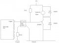
I am thinking something like a resistor and then a transistor to activate the valve.


Rich (BB code):
                          12V
                           |
                           |
---[res]-------[Trans]
                            |
                            |
                          [valve]
                            |
                            |
                         Ground
but I dont know what is the appropriate value of the resistor (or if I have to use one) and even less what kind of transistor I have to use.


If any of you has experience with Solenoid Valves, some help will really appreciated.

Kansai.
 
Last edited:

SgtWookie

Joined Jul 17, 2007
22,230
If you are going to use ASCII characters for schematics, you will find it helpful to first compose them in Notepad or other fixed-width font text editor, and then paste the schematic into your post using [ CODE] [ /CODE] (no spaces) tags wrapped around it to preserve the formatting.

We do not know where in the world that you live, as you have not put that information in your profile. This is a good thing to do, as we can make a better guess as to what parts to recommend for you to use.

PICs have limited current source/sink capability. Generally, you should ensure that no more than 20mA will be sourced from or sunk by any I/O pin. Also, you must keep the total current of the uC within the electrical specifications of the particular PIC; see the Electrical Specifications section of the datasheet.

Generally, you are pretty safe using 1k resistors on the I/O pins.

However, since I=E/R, and conversely R=E/I, you can determine by your uC's Vcc what is the minimum current limiting resistor you should use. If you're using 5v, then R=5v/20mA = 250 Ohms. This is not a standard value, but 270 Ohms is.

Here is one way to drive a relay or solenoid using a MOSFET:


You could also use a 2N2222 transistor; in that case your base resistor should be adjusted to provide 1/10th of the desired collector current.

Your solenoid requires 86mA, so you want 8.6mA base current.
Vbe (voltage from the base to emitter) will be about 0.7v; subtract that from Vcc/Vdd (5v), and you get 4.3v.
R=E/I, so R=4.3v/8.6mA = 500 Ohms.
You could use 470 Ohms or 510 Ohms, which are standard values and will be close enough.
 

Attachments

Thread Starter

KansaiRobot

Joined Jan 15, 2010
324
Hello. and thanks for the help.

I was told I must use a opto-isolator to isolate my 5V circuit (Microcontroller) from the 12V solenoid circuit.
So in the end it came to this:

However I am not sure, it seems it does not work. I measured the voltage in both sides of the solenoid. (it must be 12V when a 5V output is applied from the PIC, no?)


Can anyone comment on this circuit? and how to check if it works or not?

Thank you again in advance

Kansai
 

Attachments

retched

Joined Dec 5, 2009
5,207
Take a look at the schematic. There is 12v coming in from another point. The transistor will connect that to ground. This allows you to use the 5v 20ma from the pic to connect the 12v to ground in turn energizing the relay coil.
 

Thread Starter

KansaiRobot

Joined Jan 15, 2010
324
Sorry I dont understand.

the solenoid needs 12V to work. How can I check if it is working or not? it seems it is not..... must there be 12v between both ends of the solenoid??
 

SgtWookie

Joined Jul 17, 2007
22,230
The PS2501-x series optoisolators have a typical Vf of around 1.2V @ 10mA current.
If your uC's Vcc is 5v, then Rlimit = (Vcc-Vf)/10mA = (5v-1.2v)/10mA = 3.8/0.01 = 380 Ohms. You should be using a resistor of 380 Ohms to 390 Ohms for the emitter side of the optisolator.

Right now, with a 100 Ohm resistor, you are causing 3.8v/100 = 38mA current flow, which is twice what the output of your uC is rated for. You may have destroyed the I/O pin, or the optoisolator.

I already mentioned in my previous post that 250 Ohms was the lowest safe value of resistance to use; I guess you really don't like your microcontroller?

The 390 Ohm resistor should be between the uC I/O pin and the anode of the optoisolator's emitter, and the cathode side of the optoisolator's emitter should connect to the uC's ground.

It'll make things easier if you use the optocoupler's transistor to source current to the 2N3904. You'll still need to limit current through the base so you don't burn up the opto's output. You will also need a pull-down resistor on the base of the 2N3902 to make sure it turns off.

Like this:


Attachments

Thread Starter

KansaiRobot

Joined Jan 15, 2010
324
Thank you very much for the help.
I didnt put that resistor with bad intention :( just ignorance.
Anyway I am implementing the circuit you recommended.

Just quick question.

Don't I need a resistor of some sort in the circuit going from the 12V to the ground?? to limit the current that is going to go through the solenoid?

Dont I run the risk to fry the solenoid if I dont put a resistor???

I would really appreciate an answer on this since the solenoid is the only thing I can not burn... :(

Thanks a lot
Kansai
 

retched

Joined Dec 5, 2009
5,207
Do you have a datasheet for the solenoid? If so, find the current requirement. You can choose a resistor dependent on that. You will also need to know the current of your 12v supply.
 

Thread Starter

KansaiRobot

Joined Jan 15, 2010
324
Well in the specs it says
Operating Voltage Range 10.8~13.2 V
Current(when rated voltage(12V) is applied: 84mA
Allowable leakage current 2.0 mA
Insulation Resistance Over 100 MΩ

So I am guessing that I dont need any resistance, cause the solenoid valve has a huge resistance after all. I wonder what you think about this....
 

SgtWookie

Joined Jul 17, 2007
22,230
If you use the circuit exactly like I posted it (with the exception of the optoisolator being a PS2501-x instead of a 4N25) then it should work with no problems - as long as you have not destroyed either your uC's I/O pin or the optoisolator due to using the 100 Ohm current limiting resistor and resulting high current.
 

Thread Starter

KansaiRobot

Joined Jan 15, 2010
324
Thank you very much everybody especially SgtWookie.

I finally made it work in a breadboard. And I learned a lot about why it is working the way it is. It was an educational experience.

It is time for me to go to the third part of my project which I will post in a new thread. If you can take a look I will be honored.

Thanks again.

Kansai


P.S. By the way. My supervisor asked me if it wouldn't have possible to avoid using the transistor and the resistors on the right and just connect the solenoid directly to the photocoupler, so that this acts like a switch on/off. I guess the photocoupler has a phototransistor there so it makes sense, unless there is a amperage limitation. Any thoughts??
 
Last edited:

Thread Starter

KansaiRobot

Joined Jan 15, 2010
324
Hello!

Just to wrap it up (and one proof that I am absolute beginner!:rolleyes:) ...
I would like to add a LED in the circuit just between the PIC and the resistor (390Ω) or between the optoisolator and the ground.

the led I am using says:

average voltage 3.2V
Condition IF 20mA

I have connected a 5v in series with a 1K resistor and it turns it on....

Now in the circuit the resistor is 390 Ω... would that be safe?

Kansai

P.S.

I ve done calculations and 5v and 1K gives me what? 5mA?? if that , then why does it turns on now??
and with a 390Ω it would give me... ummm lets see 13mA??

I am lost at this.... even Ohms law....:mad:
 

SgtWookie

Joined Jul 17, 2007
22,230
My supervisor asked me if it wouldn't have possible to avoid using the transistor and the resistors on the right and just connect the solenoid directly to the photocoupler, so that this acts like a switch on/off. I guess the photocoupler has a phototransistor there so it makes sense, unless there is a amperage limitation. Any thoughts??
Your relay requires 86mA. Look at the datasheet for the optocoupler that you are using, in particular the information about the output transistor's capabilities.
 

SgtWookie

Joined Jul 17, 2007
22,230
I would like to add a LED in the circuit just between the PIC and the resistor (390Ω) or between the optoisolator and the ground.

the led I am using says:

average voltage 3.2V
Condition IF 20mA

I have connected a 5v in series with a 1K resistor and it turns it on....

Now in the circuit the resistor is 390 Ω... would that be safe?
The emitter in the optocoupler needs around 10mA. It has a Vf of about 1.2V at that current.

Current is the same in a series circuit, each component has the same current passing through it.

If you wish to operate the optocoupler and your 3.2v 20mA LED in series, you will need to operate the 3.2v 20mA LED at a lower current level.

First, you will need to determine the new LED's Vf with the reduced current.

You can do that using a known fixed or variable resistor with a fixed or variable power supply that outputs at least 5v - at least one must be variable.

Set the voltage or resistance so that the current flow through the LED is 10mA, then measure it's forward voltage.

Then add the photocoupler emitter's Vf to the LED's Vf, and subtract the sum from your uC supply voltage. Divide that result by 10mA. Your current limiting resistor must be equal to or higher than the result.

I ve done calculations and 5v and 1K gives me what? 5mA?? if that , then why does it turns on now??
(5v-3.2v) / 1000 = 1.8mA.

and with a 390Ω it would give me... ummm lets see 13mA??
(5v-3.2v) / 390 = 4.61mA - but if you have something else in series, the voltage will decrease, so the current will also decrease.

I am lost at this.... even Ohms law....:mad:
It's all Ohm's Law so far. However, you must know that even though diodes (LEDs, too) have a reasonably consistent voltage across them when a current is passed through them, the voltage drop (Vf) changes as the current changes. The greater the current, the higher the Vf. It's more logarithmic than linear, however.
 
Top