
The red LED light on my safe-T-beam box (source) is off. I checked the wires to the box has 12VDC. I open the box and check pin 1 of the IC 34198A is 2.2V when the input power is 12VDC. It is too low. I increase the input power to 24VDC, and the LED light start to blink. I am wondering what the supply voltage should be for the safe-T-beam boxes. Does anyone know?
Genie Pro Stealth garage door operator system about Safe-T-Beam devices
- Thread starter bill6631
- Start date
Scroll to continue with content
geekoftheweek
- Joined Oct 6, 2013
- 1,216
Do you have a datashhet for the ic? I did a quick search and couldn't find anything.
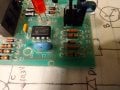
I can't find any datasheet of this IC either. Please see the attached photo on the source board.Do you have a datashhet for the ic? I did a quick search and couldn't find anything.
Attachments
-
 916 KB Views: 21
geekoftheweek
- Joined Oct 6, 2013
- 1,216
The only reason I asked is because you said 2.2V is too low and I wondered how you determined that without knowing anything about the IC to begin with. It does look from your drawings you may have done a little work tracing things out (unless that is something totally different) so maybe I was thinking wrong.
To me it would seem 24V is at the upper end of what one would expect for a control system especially in a potentially "wet" environment... kind of along the lines of the same reasons GFCI outlets are required in garages.
I wish I had an answer, but I don't
To me it would seem 24V is at the upper end of what one would expect for a control system especially in a potentially "wet" environment... kind of along the lines of the same reasons GFCI outlets are required in garages.
I wish I had an answer, but I don't
geekoftheweek
- Joined Oct 6, 2013
- 1,216
I did find a listing on alibaba for a 34198a that shows a PIC12F635.
According to the datasheet the minimum voltage is 2.0 V.
According to the datasheet the minimum voltage is 2.0 V.
I applied 12VDC on inputs and measured voltage on all pins of this IC. The highest voltage is 2.8V on pin 4, and there is a diode from pin 4 to pin 1 in forward biased. The voltage on pin 1 is 2.2V. There is a capacitor connecting from pin 1 to pin 8. Pin 8 is ground; so, I think pin 1 is the power pin as usual.The only reason I asked is because you said 2.2V is too low and I wondered how you determined that without knowing anything about the IC to begin with. It does look from your drawings you may have done a little work tracing things out (unless that is something totally different) so maybe I was thinking wrong.
To me it would seem 24V is at the upper end of what one would expect for a control system especially in a potentially "wet" environment... kind of along the lines of the same reasons GFCI outlets are required in garages.
I wish I had an answer, but I don't
The power for my garage door control system is not a GFCI outlet, but the safe-T-beam source and sensor boxes are close to the door and on the ground. They are easy to get wet.
I look up the datasheet of PIC12F635. It looks like a kind of IC to do the job.
The voltage on pin 1 is 2.2V when the input is 12VDC, and the LED light is off. The voltage on pin 1 is 2.5V when the input is 24VDC, and the LED blinks. However, according to the datasheet of PIC12F635, 2.0V on pin 1 should be good enough for this IC to work. I am going to trace how the pin 1 voltage is determined.
The voltage on pin 1 is 2.2V when the input is 12VDC, and the LED light is off. The voltage on pin 1 is 2.5V when the input is 24VDC, and the LED blinks. However, according to the datasheet of PIC12F635, 2.0V on pin 1 should be good enough for this IC to work. I am going to trace how the pin 1 voltage is determined.
geekoftheweek
- Joined Oct 6, 2013
- 1,216
The GFI comment was more about general safety than anything else. I don't think tbey are required for operators and would probably trip with certain types. I would keep the voltage as low as possible myself as a precaution is really what I meant to say.
The blinking led may be an overvoltage warning, but it seems like it should do something at 12v also.
The blinking led may be an overvoltage warning, but it seems like it should do something at 12v also.
I recall this thread
I searched it backwards because I remember Tony and I discussing this problem. The gist of my response is that I believe Genie runs on 5V, not 12V nor 24V. If yours runs on 5V I hope you didn't blow it out. And yes, the afore mentioned thread talks about the garage door switch on the wall, the point here is the 5V.It's not as think as you simple.
This is a "Series 3" wall switch. It has three buttons. First opens and closes the door (as stated before). Second is a lock to prevent unauthorized openings from the wall switch (as stated before - sort of) and a third for controlling the lights (as stated before).
The circuit line has 5.17 VDC unloaded (with the switch removed). Sitting here now I'm thinking I should have tested the voltage with it connected. I CAN do that if I need to.
I have a series 2 control switch, but when I put it on the ONLY things that happens is when I hit the door button the two garage lights come on. They go off if I push it again. The lights also come on if I push the light button - and go off with the next push. IF I push the lock button then nothing happens. No light, no other actions. When NOT locked the lights can be switched on and off. Nothing more. No matter what, a series 2 won't actuate the door. It will take a series 3 wall switch to operate normally.
So I have the S3 on the bench. According to the installation instructions there is NO polarity. Yeah, I know, 5 Vdc. I can see D3 & D4, so I assume there's also a D1 & D2. Maybe they're rectifying polarity and sending some sort of pulse back up the line - same as they do with the safety beams. Those also operate on two wires each with no polarity. They did that so the average home owner can install them without having to follow polarity.
Anyway, I'm wondering what I should test on it. IF there's any sense in testing it. I don't know what I'm looking for, nor do I know where to test for what sort of signal other than to power it with 5V and scope it.
U1 is a TI5551 chip. Assuming it's a Texas Instruments 555 timer. Though exactly how it's configured I don't know. There's (as you can see) a white membrane covering the board preventing me from tracing out the circuitry. But since the series 2 DOES actuate the lights then maybe I can conclude that since the series 3 does NOT actuate the lights either it's stuck in lock mode or the switch unit has failed.
MisterBill2
- Joined Jan 23, 2018
- 18,508
Have you gone to the manufacturers website and looked for information. Many other sites are simply pure fiction, so they will be of no use.
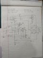
I traced the circuit and draw a diagram in the attachment. I applied 12VDC on inputs and measured voltages around. Those numbers beside lines and pins are measured voltages. There are two light-emitting diodes. One is an LED indicator. Another is IR source to sensor.
I don't understand many places on this circuit.
1) Not sure how the Q1 work. Q1 is an NPN transistor. There is a diode between Base and emitter with cathode to base. This makes Vbe negative. this transistor will never be on.
2) D3 is an IR diode. I measured a diode 0.7V drop. Is it have to be reverse bias to emit IR?
The Vb of Q2 is too low to turn on this transistor because the voltage on pin 5 of U1 is too low. So, Vc stays high voltage, and D3 IR does not emit light. The problem is U1 IC. Is it correct?
Attachments
-
 911 KB Views: 20
MisterBill2
- Joined Jan 23, 2018
- 18,508
The applied voltage is not adequate. First, the Ac voltage range mentioned is RMS or average, not peak, which the 12 VDC supply is equal to. So there is one problem. THAT is at least partly why the measured voltages are too low. So that should help your problem analysis work.
If you must supply DC, give it 20 volts DC.
And feeding it an AC voltage will be the better choice.
An insufficient supply voltage will certainly reduce the value of voltage measurements.
Q1 and D9 look a lot like a voltage regulator circuit, with D9 being a zener diode.
AND, since it previously was working but now is not working, a part failure is the probable cause. That unmarked electrolytic capacitor near Q2 in the drawing is a suspect, as I see it.
prairiemystic
- Joined Jun 5, 2018
- 307
D9 is a 5.6V 500mW zener diode 1N5232 which makes Q1 a 5V regulator, internally a 5V rail.
I would suspect D9, R4. If Q1 is getting hot then something downstream has shorted, and that is really only the PIC.
I would suspect D9, R4. If Q1 is getting hot then something downstream has shorted, and that is really only the PIC.
MisterBill2
- Joined Jan 23, 2018
- 18,508
A filter capacitor with excess leakage will certainly also cause excess current draw.
And my comment about the supply voltage still stands.
And my comment about the supply voltage still stands.
prairiemystic
- Joined Jun 5, 2018
- 307
The electrolytic cap is located at the regulator's input where OP measured +10.3V so it's not loading down things.
The 5V regulator (Q1) output is only 2.2V and giving max 20V makes me squirm, only R4 would be helping more then and if Q1 fails it will blow up the PIC. When I see a one transistor regulator sitting there like this, it's usually overloaded (Q1 hot) or a bad zener. OP could remove Q1 and see if D6 comes up to 5.6V to test it, leaving Q1 or the PIC as the problem.
The electrolytic cap could be low value though, letting IR pulses cause too much ripple.
Garage door openers supply obstruction sensor power through a big resistor from their DC usually 12-24VDC, and this (loop voltage) is monitored at both the opener and sensor side to ensure it's in range, for functional safety.


