Fixing Old School Dart Board

Thread Starter

k5 blazer

Joined Dec 1, 2019
26
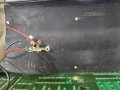
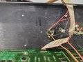
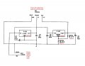
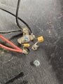
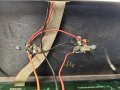
I am looking for a little help here as I am no electronics specialist. What I have here is power that feeds a circuit board. What appears to happen is that power comes in at 17ish volts. and then lands on two voltage regulators. There appears to be some caps and resistors in line here but I really don't understand what is happening with all that. All I know is on the input side of the regulators I have 17ish volts to ground and nothing on the output side. So I wonder if the regulators are shot or some of the caps or resistors. Any help describing what is going on electronically would be greatly appreciated.

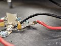
What I believe is supposed to happen is that the red to ground and orange to ground provides two different voltages to the circuit board. I get zero volts on the output side of the regulators to ground

If there is a better spot to post this please feel free to let me know.
 

Attachments

Jerry-Hat-Trick

Joined Aug 31, 2022
596
It’s difficult to see from your photos exactly what is going on. The two devices could be voltage regulators but also just transistors. Can you read the part number on them? Maybe take a close up photo of each.

On the wiring side, where are you measuring 17 volts? and again, it would help if you could take a photo close up of each, ideally at an angle where the components can be clearly seen and they are all connected together. On which wires are you expecting to see the two different voltages and do you know what they should be?
 

Ya’akov

Joined Jan 27, 2019
9,277
They are LM323K and LM338K regulators—5V, 3A and adjustable, 5A respectively.

The datasheet suggests the LM323K is “practically impossible to blow out” because of internal current limiting and thermal protection.
 

Thread Starter

k5 blazer

Joined Dec 1, 2019
26
So the three wire come together at a connector that plugs into the circuit board. That would be the orange, red, and black wire. On these sides of the regulators "output side" I have no voltage, on the Input side I have voltage. I will see if I have any better photos of the resisters, diodes and caps or what ever they are. I might have to tear it back apart to get them.
 

Thread Starter

k5 blazer

Joined Dec 1, 2019
26
These are little better of an idea or closer up. Notice this stuff was all lose and not bolted in place. This is how I receive the dart board and I suspect a direct short at one time. The regulator pins rest right against the metal back plane which is ground etc.
 

Attachments

Thread Starter

k5 blazer

Joined Dec 1, 2019
26
When I desolder the wires/devices from the output side:

LM323K input side to ground had 16.82v and from output side to ground 3.8mv and dropping down to like 1mv

LM338K input side to ground had 16.79v and from output side to ground 15.69v
 

Thread Starter

k5 blazer

Joined Dec 1, 2019
26
So I believe I need to start with a new LM323K, That said I see pricing all over the map $2 to $60. Are all LM323K created equal? Any recommendations for a reliable source where to purchase from
 

Thread Starter

k5 blazer

Joined Dec 1, 2019
26
OK guys needs some further direction.On the LM338K I resoldered the resisters on to the voltage regulator and I get no voltage. So I started checking continuity between things. Should I be able to read continuity through the small round caps red to ground at either regulator? The bigger square caps do not ring continuity throgh them...

I am pretty sure the LM323K is dead and I have ordered a new one.

Now maybe some cap issues?

thanks in advance
 

Attachments

Dodgydave

Joined Jun 22, 2012
11,393
Remove the regulators from the heatsink, and solder the resistors on the regulators and see if the voltage is correct, to check if it's working, if so transfer it to the heatsink.
 

Thread Starter

k5 blazer

Joined Dec 1, 2019
26
All still needs some help here. I have replaced the LM323K with a replacement and I am now getting solid 5v that was expected. I am still having issues with the LM338K where I expect 12v.

As mentioned in previous post above, LM338k works with 16.79 on the input and about 16v on the output with no load. As soon as I attached the the first resistor of 866ohms, it pulls the out put down to about 420mv. Is this a indication that the LM338k is failing under load
 
Last edited:
Top