Equation for capacitor discharge

Thread Starter

pastaperson

Joined Nov 1, 2009
2
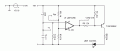
I've got the following circuit here:


I want to find an equation to model the capacitor discharging. If I'm correct, this is the needed equation:

V = V0 * e^(-t/RC)

In my case, I am using a nine volt battery, 1K resistor and 5μF Capacitor. When I calculate the RC I get 0.064, which surely can't be right here?

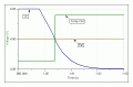
I'm using Circuit Wizard, and this is the output of graph when it runs on the three probe points (as above):


Basically, when the equation for the capacitor discharges meets the equation of the voltage divider, the LED will turn off. I'm trying to find this equation so that I can include it in my write up.

Thanks for your help
- pasta
 

t_n_k

Joined Mar 6, 2009
5,455
In the interests of circuit predictability, the 1k should probably be in series with the switch to limit the current pulse magnitude drawn from the 9V supply when the switch is pressed - otherwise you have an effective momentary "short circuit" when C is even partially discharged.
 

Thread Starter

pastaperson

Joined Nov 1, 2009
2
In the interests of circuit predictability, the 1k should probably be in series with the switch
I've since fixed that. Its meant to act as a debounce, so I am pretty happy with the way it discharges.


Your image doesn't show a 9V discharge curve. The tau is only 5 milliseconds and the 9 V should have decreased to zero in about 25 milliseconds.
What I'm confused with is 0.064 and why it isn't discharging correctly? I'm assuming the formula is correct here, but I'm missing something with my circuit?

When I graph 9 * e^(-1/0.064) over the domain [0, 1], I get the following image:


Which certainly fits what JoeJester was saying
 

Jony130

Joined Feb 17, 2009
5,599
To proper "discharge" you need to add resistor parallel to C1 to get good discharge path.
Now capacitor is discharge by base current of LM741 and this current is very small typ. 20nA, max 200nA.
So to discharge 5uF capacitor to 0V you have to wait
C=Q/U=I*t/U

t=(C*U)/I=(5uF*9V)/200nA=225s


For example, if we have a capacitor charge to Vcc=9V and we wont to discharge capacitor to Vc=4.5V at time t=5s
We need parallel resistor R

\(R=\frac{t}{C*In(\frac{Vcc}{Vc})}=1.5M\)

R = t / ( C*In(Vcc/Vc) )
= 5s / ( 5uF * In(9/4.5) )= 5/(5uF*0.693)=5/3.465u=1.44MΩ=1.5MΩ
 
Last edited:

JoeJester

Joined Apr 26, 2005
4,390
If you want the LED to energize when you press the switch and then de-energize after a delay when you release the switch, you might want to use the circuit illustrated in the 091101_B picture. 091101_A illustrates the waveforms.

If you want delay energizing the led, (less than one tau), then place the resistor in series with the switch.

The resistor placement in the OPs diagram is in series with the High-Z OPAMP input, making the discharge path the Input Z and the resitor.
 

Attachments

Top