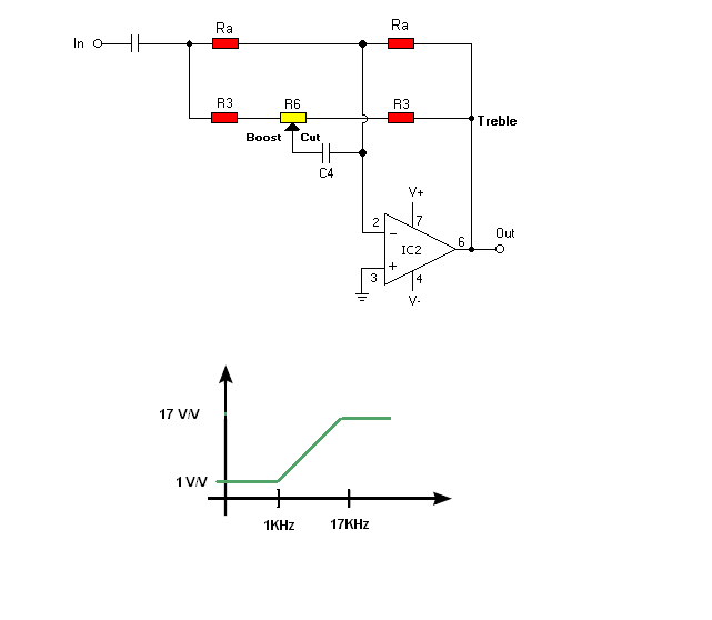
I'm looking for formulae for the equalizer filter (see attachment). It is almost a T-filter but not exactly. Measured frequency of this filter is 600Hz (the pot is 100k).
Great - this exactly what I needed . Can you point me to any reference about the design? I need also Q-factor and gain/cut formulae.
I don't need to mention that the formula matches exactly measured values. Thank you very much.
EDIT: you were quicker (providing the Q-factor formula). Shouldn't there be R12 = 10* R2?
I think that there is a small mistake in the substitution. It should be R12 = 100*R2,which leads to a different formula. Can you look at it?
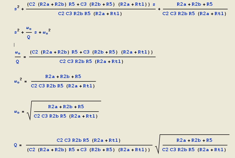
My formula looks like this:
\(\omega _o = \frac{1}{sqrt{1010}*R2*C4} * sqrt{1 + 2*\frac{R2}{R1}}\)
and it seems to yield the same results as the previous one.
Does it change the Q-factor formula?
The only reference I know is
"Design with operational amplifiers and analog integrated circuits" Sergio Franco.
But a few months ago,with help of Mathematica software, I analyzed this circuit:
Thanks for all explanations. Accidentally I also analyze this curcuit (but with SPICE simulator and not Mathematica). Although it is similar to my curcuit, I did not like it. It's because the TREBLE pot has a great influence on the MID frequencies filter. And, as a result, it does not sound good .
Hmm, in my circuit POT (R1) = 100k, R12 = 220k and R2 = 2.2k. I'm confused where did you take 1M from. So R12 meets the condition: R12 = 100 * R2, but definitely R12 is not equal to 10 * R1 . And the resulting frequency is 594Hz (both measured and calculated from the first formula). Am I missing something?
No, I haven't tried it (I may check it). The article from TI explains why this circuit is not very good. R7 = 100R creates a high frequency roll-off (page 2) and 10k pot does not have expected logarithmic effect (page 5). Although they say that 10k low value pot solves this problem, but it doesn't (I checked it).
Somehow my circuit handles these 2 problems correctly . That's why I'm working on it.
PS: I wanted to send you a PM but it seems that new members are not allowed to send private messages. In that case: "Bardzo dziękuję za pomoc".
Hmm, in my circuit POT (R1) = 100k, R12 = 220k and R2 = 2.2k. I'm confused where did you take 1M from. So R12 meets the condition: R12 = 100 * R2, but definitely R12 is not equal to 10 * R1 . And the resulting frequency is 594Hz (both measured and calculated from the first formula). Am I missing something?
No, I haven't tried it (I may check it). The article from TI explains why this circuit is not very good. R7 = 100R creates a high frequency roll-off (page 2) and 10k pot does not have expected logarithmic effect (page 5). Although they say that 10k low value pot solves this problem, but it doesn't (I checked it).
Somehow my circuit handles these 2 problems correctly . That's why I'm working on it.
Well, all circuit have some drawbacks, your circuit for example has a low Q factor. So if you want to build more then six bands equalizer, you are forced to use Active inductor circuits.
OK, I get it. But it means that several other components need to be changed too; R12 = 1M, R2 = 10k (otherwise gain is more than 20dB), capacitors C4= 900p, C3 = 9n (to keep the frequency at 600 Hz). As a result the Q-factor is even slightly lower than before.
Being frankly, I don't want to build a 31-band equalizer. I want to have just 3 bands (later maybe I will try 5 bands). And I want to have each filter to be independent from the other filters (as much as possible). I want to have gain/cut at 13 dB or less. It seems that this is quite a complex task since change of one component value influences several parameters.
Yes, I have to use the complex version of the formula. I still have some problems with Q-factor. I get values about 10% different from measured in SPICE but maybe I'm not measuring the bandwidth correctly.
Yes, I know but with 3-bands EQ this shouldn't be a problem. I hope to be able to use this circuit with 5-bands too.
Jony can you send me PM - maybe this topic is interesting to others.


") . Can you point me to any reference about the design? I need also Q-factor and gain/cut formulae.
. Can you point me to any reference about the design? I need also Q-factor and gain/cut formulae.