Elliptic Low pass filter design

Thread Starter

tblues87

Joined Apr 9, 2013
11
Hi

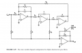
can someone suggest which design to use for active low pass filter 4th order. I have tried Tow - Thomas filter (Biquad filter) with 4 op amps 2nd order in cascade, but the ripple in pass band isn't 1 dB as I want but 0.9 dB and has two peaks over 0 dB.

Thanks
 

Attachments

Papabravo

Joined Feb 24, 2006
21,225
Well the basic message is that filters are "designed" by articulating the requirements and then refining the design if the requirements are not met in practice.
 

Thread Starter

tblues87

Joined Apr 9, 2013
11
I noticed that as I increase frequency the oscillations in pass band are getting bigger and as I decrease frequency opposite happens and so for pass band freq. = 400 Hz I get perfect result but my frequency is 4000 Hz.

Can you give me some advice on that problem?
 

Papabravo

Joined Feb 24, 2006
21,225
Where do you think to corner frequency is located? It is not unusual to have substantial ripple in the stopband, but it is usually 60-80 dB down.
 

Thread Starter

tblues87

Joined Apr 9, 2013
11
These are specifications that I working with:
Ap=1dB (ripple in pass band)
fp=4000 Hz
As=40dB (max attenuation in stop band)

Below are amplitude responses for
1. fp=400Hz
2. fp=4000Hz
3. fp=40000Hz

You can see only the pass band and for fp=400 Hz I get the best result, but as the frequency rises it goes worse?
 

Attachments

Papabravo

Joined Feb 24, 2006
21,225
When you specify the allowable ripple in the passband you are setting a maximum which includes both loss and gain. If the actual ripple is less than that so much the better. At low frequencies there is a loss of 0.9 dB and just below the corner a 4.0 kHz you are just above 0.1 dB of gain for a total ripple of just over 1 dB.

At 40 kHz the total ripple is 2.0 dB - (-0.9 dB) = 2.9 dB, clearly not meeting your requirement. What amplifiers are you using and what is their frequency response? Are the plots from actual breadboards or are they simulations?
 

Papabravo

Joined Feb 24, 2006
21,225
From an examination of the datasheet, two questions:
  1. Would you build a real opamp circuit without bypass capacitors?
  2. Did you provide for offset nulling?
I can't tell if the model will care about these two things but the real part damn skippy will!

The unity gain bandwidth is 3 MHz. Is there any evidence of clipping in any of the stages?
 

Thread Starter

tblues87

Joined Apr 9, 2013
11
At the end I probably would build filter on breadboard, but which of there are bypass capacitor and if you could tell me importance of them.

As I have been reading offset nulling is done only in real op amp with appropriate pin or am I wrong?

Here are amplitude responses for each section from LTSpice IV and Matlab.
I may be wrong but there is no clipping?

One more question.
These are my transfer functions

\(H1(s)=0.1\frac{s^2 + 2.590653}{s^2 + 0.728581s + 0.361768}\)

\(H2(s)=0.1\frac{s^2 + 12.427609}{s^2 + 0.210562s + 0.008545}\)

to find the gain of each section does it need to be in this form

\(H1(s)=0.716109\frac{1 + 0.386003s^2}{1 + 2.013945s + 2.764202s^2}\)

so the gain of first section is 0.716109

This is important to me when I'm calculating elements so sections don't have unity gain.
The procedure for calculation of elements is in
Electronic filter design handbook
Thanks
 

Attachments

Papabravo

Joined Feb 24, 2006
21,225
What I was looking for was something that would produce higher than expected gain causing the ripple to exceed your requirements. How did you apply the ripple condition, |Ripple| <= 1.0 dB and how did it affect the transfer functions and the component selection.

Bypass capacitors go from Vcc to GND and from Vee to GND. The purpose is to suppress high frequency noise that could make a gain stage oscillate. If all your stages have less than unity gain then there must be some other interaction (resonance(?), or phase shift(?), or delay(?)) that is causing the response to exceed the 0 dB level.
 

Thread Starter

tblues87

Joined Apr 9, 2013
11
The ripple in pass band is given by Rp =1 dB and I don't know how it affects the transfer function because I got it with matlab function ellipap(Ap,As,N), in which Ap is ripple in pass band, As max attenuation in stop band and N is the order of filter. With this function I got poles, zeros and gain of 4. order elliptic filter.

Poles are
\(p_1= -0.364291 + j0.478603 \)
\(p_2= -0.364291 - j0.478603 \)
\(p_3= -0.105281 + j0.993711 \)
\(p_3= -0.105281 - j0.993711 \)

zeros
\(z_1= j3.525287 \)
\(z_2= -j3.525287 \)
\(z_3= j1.60955 \)
\(z_4= -j1.60955 \)

and gain for 4th order
k=0.01

From here I paired p1 and p2 with z3 and z4 and that gave me transfer function of 1st section and reaming poles and zeros paired for second section.

The gain I divided to be equal for each section 0.1.

If all your stages have less than unity gain then there must be some other interaction (resonance(?), or phase shift(?), or delay(?)) that is causing the response to exceed the 0 dB level.
The second section is

\(H2(s)= 0.1\frac{s^2 + 12.427609}{s^2 + 0.210562 + 0.998545}\)

if the other form

\(H2(s)= 1.244572\frac{1 + 0.080466s^2}{1+ 0.210869s + 1.001457s^2}\)

so the gain is 1.244572
 

Papabravo

Joined Feb 24, 2006
21,225
So what we are left with is a situation where you ask Matlab to design a filter with a constraint and then we check the design to meet the constraint and we discover that it does not satisfy the initial constraint when you implement the design with "models" that represent real components.

Gains of the sections do not suggest that you are exceeding the specifications of the components in tems of Gain-Bandwidth product which at 3 MHz (The Unity Gain Bandwidth) should be sufficient at 40 KHz.

What about slew rate? IIRC 12 volts/usec should allow 40 kHz operation without any trouble.

Can you use an ideal opamp in your simulation to see if you get different results? I don't know what else to suggest at the moment.
 

Thread Starter

tblues87

Joined Apr 9, 2013
11
Even when I'm using ideal op amp, only three pins (inverting, non-inverting and output), I don't get right amplitude response, better but it should be like in matlab.

This is the first time that my LTSpice IV model isn't as one in matlab.

Thanks
 

Attachments

If the opamps are ideal in that their frequency response is flat to many megahertz, but their gain is low, your topology will exhibit gain peaking. Here's the response with such opamps and with gains of 100 (red), 300 (magenta) and 100000 (blue).


With a single pole rolloff and 3 MHz GBW, the response is almost the same as the blue curve in the previous image.

But, if the opamp response is what one might get after compensating the opamp, for example like this:


then the filter response is like this (shown in red with the ideal gain in blue for comparison):


This gain peaking is due only to the opamp response deviation from ideal.

I suspect your deviations from the ideal are due to opamp limitations. You could determine the typical frequency response of the opamp you will be using and compensate for its effect on the filter response by tweaking the pole and zero locations in your filter transfer function.
 

Attachments

Even when I'm using ideal op amp, only three pins (inverting, non-inverting and output), I don't get right amplitude response, better but it should be like in matlab.
Be aware that Spice components often are not ideal even when they should be. For example, if you try to set a resistor's value to zero ohms, it won't be exactly zero ohms; it will probably be a value of some microohms. Spice does this to avoid situations where convergence is slow or non-existent.

It's possible that your "ideal" opamp in spice is not really ideal. You might plot its frequency response and see how "ideal" it is.
 

Thread Starter

tblues87

Joined Apr 9, 2013
11
Thank you very much

I replaced TL071 with LM118 and got better results.

One more question can you suggest me maybe some other op amp like LM118 because the stores in my town don have it?

Thanks
 

Attachments

Top