
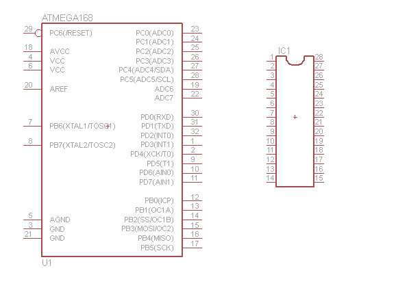
I working on my first PCB eagle file and am confused. In the attached image, on the left is a pin out for the ATMega168 (same pin out as 328). On the right is a 28 pin socket for the ATMega.
I don't understand how the pins on the ATMega related to the socket. I was expecting 14 or less on each side.
Thanks!
I don't understand how the pins on the ATMega related to the socket. I was expecting 14 or less on each side.
Thanks!


