
Hi All,
I hope some would be able to help. I know the post is really long but please bear with me and read through you would find the project to be interesting!
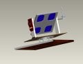
I have a solar tracker project that I am working on right now. Its a dual axis solar tracker that I am building at them moment. The two axis are turned using 2 separate 12Volts DC motors which obviously are powered from a 12Volts XAmpsHour lead acid battery. I am a complete noob in electronics so please bear with me. Having a mechanical background the manufacture and building of the solar tracker was not a problem and have completed that already. I do not have the real pictures of the already manufactured tracker prototype but the PRO/E designs.
Please see the attachment below to understand the prototype better.
Attachment description: Assembly view of the solar tracker. Note the worm gear on the left, the sensor on the right, and a turntable bearing at the bottom. Also note that vertical axis motion is not displayed here. That axis (or the shaft on that axis) would be coming just from the middle of the turntable bearing to the top of the absolute base (which is shown in wodden appearance here). Design made and analysed for typical stresses and motor torque requirements on Pro / E.
Right now I am trying to do the PCBs. Basically, there are going to be 4 PCBs (Can have one single PCB and all circuitry in it but I am just going to go with separate PCBs for separate workings).
So, I am using 4 PCBs namely:
East-West Motor - Circuit here
North-South Motor - Circuit here
Sensor (short one going straight on the prototype's assembly)
Voltage regulator for battery charging purpose - Circuit here
I have almost done the mechanical part for my solar panel and I am working on eletronics for now.
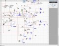
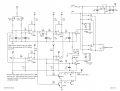
I have not created my own circuits but using the one I found on the internet. That is because I have absolutely no electronic background. I will acknowledge same in the technical project report. But still I am seeing that I have to tweak those circuits for my need. For example, the East-West PCB above has a time delay. The capacitor in this circuit, that is the backbone in running the motor, charges up really slow and in this circuit it takes about 100-120 minutes or more to run the motor every time the sun creates a shadow on the east facing sensor. This cycle repeats again once the motor have run and normalised the resistance difference between the two LDRs.
I have reduced the capacitance from 1000μF to 10μF, and the simulation on Multisim software shows the delay rectified but now the motor runs every 10 minutes or so which again is a pain.
I have to tweak all those PCBs to my prototype's requirement and unfortunately this is turning out to be a nightmare for me
The problem in the East-West circuit is that during the night time when I adjust VR2, LED1 never lits but the relay RL2 definitely gets energised at some value of VR2. According to the author of this circuit, I am just going to quote his written advise- "At the end of the day adjust VR2 to the point LED 1 will just turn ON. Start with the trim pot set at GND. Turning it towards +9V increases the circuit's sensitivity to light." The LED1 never lits-up at any position of VR2.
Pardon me if I am missing something here! But would you please be able to advise, how can this be rectified? I have not created the PCB yet, I am only simulating this circuit on National Instrument's Multisim software and it is kind of doing the job for now. I just want to make sure everything would work just fine, before coming to the real world and doing the PCB itself.
Any piece of advice would be highly appreciated!
regards
prem25
I hope some would be able to help. I know the post is really long but please bear with me and read through you would find the project to be interesting!
I have a solar tracker project that I am working on right now. Its a dual axis solar tracker that I am building at them moment. The two axis are turned using 2 separate 12Volts DC motors which obviously are powered from a 12Volts XAmpsHour lead acid battery. I am a complete noob in electronics so please bear with me. Having a mechanical background the manufacture and building of the solar tracker was not a problem and have completed that already. I do not have the real pictures of the already manufactured tracker prototype but the PRO/E designs.
Please see the attachment below to understand the prototype better.
Attachment description: Assembly view of the solar tracker. Note the worm gear on the left, the sensor on the right, and a turntable bearing at the bottom. Also note that vertical axis motion is not displayed here. That axis (or the shaft on that axis) would be coming just from the middle of the turntable bearing to the top of the absolute base (which is shown in wodden appearance here). Design made and analysed for typical stresses and motor torque requirements on Pro / E.
Right now I am trying to do the PCBs. Basically, there are going to be 4 PCBs (Can have one single PCB and all circuitry in it but I am just going to go with separate PCBs for separate workings).
- Motor Description:-
- Horizontal Axis / Vertical rotaing plane / East-West
12 Volts DC motor
15 RPM
Worm gear attached. Motor on driver shaft, i.e. worm. Solar panel on driven shaft, i.e. Gear. 120 Worm turns give 1 full gear rotation. Panel would require gear's half rotation, i.e. 60 worm rotations during daytime and 60 back each day (i.e. to come back to east position whilst evening / night). As per the inertia, torque requirement calculations this DC motor will supposedly be satisfactory for the job.
During the daytime 60 worm rotations are to be distributed in such a way that highest efficiency is achieved and also the panel is kept almost normal to the falling sunlight. The sensor is designed by understanding the fact that light source is at infinity means the light rays would fall parallel to each other, i.e. flat earth theory and right angle triangle sensor calculations. Basically looking at 180 degrees I thought when every 5 degrees or so the sun moves, my panel should move itself too, to make the difference 0 degrees again. So using right angle theorem I know the inside angle of my right angle triangle also I can assume the length of the shadow in between the sensors to be 100 units or so. Now I know one angle and length of one side of my right angle triangle, I would be able to calculate the other side, i.e. at what horizontal distance from the centre of the shadow blocker the sensor(s) should sit. This gave me 8.75 units (100 * tan 5), which means when my shadow blocker's vertical length is 100 units and the sun moves 5 degrees from the centre to either side, the shadow would appear at approximately 8.75 units on the opposite side of the shadow blocker moving horizontally. The thing important here is that this shadow moves horizontally from the 'centre and extreme bottom' of the same. SO this means every 5 degrees I would like my motor to run, i.e. 180 / 5 = 36 intermittent short-term runs distributed throughout the day-time. And one sole 180 degree run whilst the evening/ night to get the tracker back to east facing position.
- Vertical Axis / Horizontal rotating plane / North-South
12 Volts DC motor
2 RPM
Bevel gear attached. Gear ratio is 2:1, i.e. every two turns of the motor would give one full rotation to the assembly. Which would never be required. I am just having this second axis because of the sun's orbit that supposedly changes during the second half of a year.
So, I am using 4 PCBs namely:
East-West Motor - Circuit here
North-South Motor - Circuit here
Sensor (short one going straight on the prototype's assembly)
Voltage regulator for battery charging purpose - Circuit here
I have almost done the mechanical part for my solar panel and I am working on eletronics for now.
I have not created my own circuits but using the one I found on the internet. That is because I have absolutely no electronic background. I will acknowledge same in the technical project report. But still I am seeing that I have to tweak those circuits for my need. For example, the East-West PCB above has a time delay. The capacitor in this circuit, that is the backbone in running the motor, charges up really slow and in this circuit it takes about 100-120 minutes or more to run the motor every time the sun creates a shadow on the east facing sensor. This cycle repeats again once the motor have run and normalised the resistance difference between the two LDRs.
I have reduced the capacitance from 1000μF to 10μF, and the simulation on Multisim software shows the delay rectified but now the motor runs every 10 minutes or so which again is a pain.
I have to tweak all those PCBs to my prototype's requirement and unfortunately this is turning out to be a nightmare for me
The problem in the East-West circuit is that during the night time when I adjust VR2, LED1 never lits but the relay RL2 definitely gets energised at some value of VR2. According to the author of this circuit, I am just going to quote his written advise- "At the end of the day adjust VR2 to the point LED 1 will just turn ON. Start with the trim pot set at GND. Turning it towards +9V increases the circuit's sensitivity to light." The LED1 never lits-up at any position of VR2.
Pardon me if I am missing something here! But would you please be able to advise, how can this be rectified? I have not created the PCB yet, I am only simulating this circuit on National Instrument's Multisim software and it is kind of doing the job for now. I just want to make sure everything would work just fine, before coming to the real world and doing the PCB itself.
Any piece of advice would be highly appreciated!
regards
prem25
Attachments
-
 302.1 KB Views: 153
 -
 178.2 KB Views: 793
 -
 27.9 KB Views: 105


