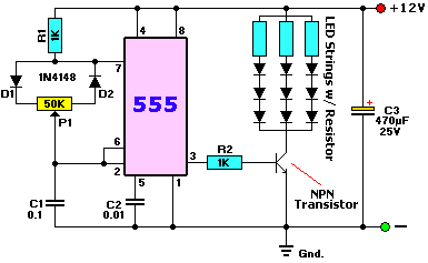
Dimmable USB powered LED circuit

Thread Starter

marmil

Joined Oct 31, 2009
28
A friend and I followed the information and suggestions in this thread:
http://forum.allaboutcircuits.com/showthread.php?t=13426
and successfully made a circuit (with a 12V power supply) to dim two LEDs. Woohoo, we were proud of our small success (both being amateurs). :p

My question: How could a similar sort of dimming circuit be made to work with standard USB 5V as the power supply?

I have two of these USB powered LED lights:
http://www.siig.com/ViewProduct.aspx?pn=AC-LG0012-S1
My goal is have a circuit that can dim these two LEDs simultaneously that I can plug into a USB port for power.

Thanks
 

retched

Joined Dec 5, 2009
5,207
You would need to provide a PWM signal to the usb lamp.

I dont know if you can do this in software on the PC side, a I haven't seen a way to turn the usb power on and off that fast.

SO, you could use a 555 pwm circuit that plugs into the port, is adjusted by a POT, and switches the power on a usb jack you install on the circuit.
 

Wendy

Joined Mar 24, 2008
23,421
The problem the OP is facing is 555 Hysteretic Oscillators don't work well so close to their limits. A CMOS 555 could do it, but it has drive problems.


Replace the NPN transistor with a logic level nMOSFET, drop R2 down 100Ω, use a CMOS 555, reduce the LEDs to 1 LED per string and it should work as is.

There are other ways to do this, but it will require more parts.
 

retched

Joined Dec 5, 2009
5,207
CMOS was my thought. And mosfet capable of 500ma also.
But Bill, I knew we could count on you. ;)
 
Last edited:

Thread Starter

marmil

Joined Oct 31, 2009
28
Retched and Bill, thank you for your posts.

...
SO, you could use a 555 pwm circuit that plugs into the port, is adjusted by a POT, and switches the power on a usb jack you install on the circuit.
Yes, this is the way I would like to go--with two usb jacks on the circuit that I can just plug those little lights into.

I plan to put the circuit board inside a little plastic box that can sit on a desk. I'll drill two holes in the box to snake the lights out of. The box can protect the circuit, provide a mounting point for the pot and a power switch, and also provide a weighted base to support the outreaching lights.

When I get home tonight I'll make a new circuit diagram based on your suggestions and post it back here for review.
 

Bernard

Joined Aug 7, 2008
5,784
If the total drain is only 1/4W, why not just use a 100 ohm pot and a 100 ohm resistor? , only adds another 1/8 W load.
 

Thread Starter

marmil

Joined Oct 31, 2009
28
Hello guys. Here's my start at it. (Not sure how to properly draw the nMOSFET symbol there.)
Bill, after reading your post again I'm not sure if your "drop R2 down 100Ω" meant from 1K to 900Ω, or down to 100Ω.
Bernard, thank you for your suggestion too. I'm happy to hear all ideas and critique.
 

Attachments

retched

Joined Dec 5, 2009
5,207
Well, your getting a hold of this pretty quickly. Im guessing this isn't your first project?

And Bill meant to drop it TO 100 ohm.
 

Wendy

Joined Mar 24, 2008
23,421
MOSFETs have a high capacitance on the gate. If it wasn't for that they would take almost no current altogether.

The gate resistor (which should be as close to the MOSFET as possible) is there to prevent ringing, where the inductance from the wires going to the MOSFET combine with the capacitance of the MOSFET to make the input ring like a bell, and incidentally turning the MOSFET on and off very quickly.
 

Thread Starter

marmil

Joined Oct 31, 2009
28
Well, your getting a hold of this pretty quickly. Im guessing this isn't your first project?
And Bill meant to drop it TO 100 ohm.
I'm a computer artist in the animation business so I'm good at making nice looking images,
even if I don't always fully understand them. ;) Thanks for the clarification on that resistor.

Would this MOSFET work for this project?
http://www.radioshack.com/product/index.jsp?productId=2062618
If not, or if you'd suggest something else please redirect me.

I guess the other thing is figuring out what ohm resistor is needed for R3 and R4. Any suggestions/what's a good way to figure that out?

Guys, thank you for not only helping, but expounding on your info and even explaining what's happening. Very nice.
 

SgtWookie

Joined Jul 17, 2007
22,230
Oops - you seem to have the USB connectors in the circuit between the MOSFET drain and the current limiting resistors.

The LEDs need to be there instead. The USB port supplies the power to the circuit.

Nope, the IRF510 won't work; as it is a standard level MOSFET requiring Vgs=10v to turn fully ON. Vgs = the voltage on the gate terminal, with respect to the source terminal.

Very generally, International Rectifier MOSFETs that begin with IRF are standard level (requiring 10v to turn on) and IRL are the logic level MOSFETs.
 

Wendy

Joined Mar 24, 2008
23,421
If you read what I wrote I refereed to a logic level MOSFET, which is a different animal indeed. They are designed for low voltages, unlike conventional MOSFETs.
 

Thread Starter

marmil

Joined Oct 31, 2009
28
Thanks SgtWookie. Sorry for the confusion--I've updated the drawing a bit to better clarify my project.

I removed the resistors that were next to the USB plugs since I figure the USB lights I'm plugging into them must have their own resistors in-line under the plastic molding somewhere, since they can just be plugged into a 5V plug and work. Does that make sense?

Also, I added an additional resistor and LED leg on the right near the switch for the purpose of indicating when power is switched on. Does that look alright?
 

Attachments

Wendy

Joined Mar 24, 2008
23,421
I have several projects out there for a 555. One that might work for your application is the CMOS 555 Long Duration LED Flyback Flasher. It will power a chain of LEDs off of a low voltage.

I would build your existing design though, and if you want to play with it later you can.

Are you familiar with protoboards? They are great to test electronics designs, the hands on alternative to simulators. If you don't blow the parts up you can reuse them. :rolleyes: :D
 
Top