Hello. I just want some feedback if is possible for my coursework so far. Also, i just want to know if the equations are correct to design the circuit in Digital Works 95.
The Problem:
Design a circuit to take binary inputs and display a number on the counter. The counter needs to display the number 1 followed by 7 to indicate the current year the coursework was done (i.e. 2017). Then this will be followed by your unique student ID number (person number). This will mean that everybody will have a unique problem to solve as no two students have the same student number. So if your student number was 123456 then your counter would need to display 17123456. Build a circuit using only AND, OR, NOT, NAND and NOR logic gates to simulate the counter. You should use 3 sequencers (I used 4 sequencers because i have 8 in my student ID) or bit generators in your circuit as input. Draw your circuit using Digital Works 95. The numbers should change automatically without any user input.
Attachments
-
 30.2 KB Views: 274
 -
 31 KB Views: 297
 -
 24 KB Views: 296
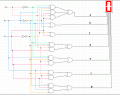
") . I have done it successfully with 3 sequencers. You do not need 4 sequencers to represent numbers 8 and 9 with Digital Works 95. Here is my circuit with the correct numbers of my student ID.
. I have done it successfully with 3 sequencers. You do not need 4 sequencers to represent numbers 8 and 9 with Digital Works 95. Here is my circuit with the correct numbers of my student ID.