Design and simulation of a differential cross coupled oscillator for 13.56 MHz using LT Spice - Help needed

Thread Starter

mishra87

Joined Jan 17, 2016
1,036
Hello Guys,

I want to do design and simulation using of a differential oscillator for 13.56 MHz using LT Spice for RFID applications.
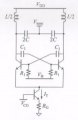
I got reference schematic from google but still i do not know the value and biasing component.
Could anybody help me in schematic design and simulation using LT spice tool?

Below is the specification :

Specifications :
- Output voltage (differential) greater than 1 V peak-peak;
- 2V power voltage; maximum current absorbed 2 mA.

Assumptions:
- Use only bipolar transistors type 2N2222
- Use a differential 2.2 uH inductor consisting of two identical halves: the central socket is used to provide battery voltage;
- take the magnetic coupling between the two halves of the differential inductor of about 0.8;
- assume that the void merit factor of the isolated resonant is at least 50;
- implement the current generator on emitters using "current mirror"

Thanks in Advance !!!
 

Attachments

Thread Starter

mishra87

Joined Jan 17, 2016
1,036
Here you go. I used the same 20 pF capacitors. If you really want to build this generator, then adjust the frequency with inductances.
Thanks again for your quick support.

Sorry I am not that much good in LT Spice so i have a few query to be answered.

1585463199558.png
1. I assume C1, C2, C3, C4 value are same and it is calculated using above formula.

2. Could you explain the use case of each parameters of below.
1585463313845.png.meas T1 =? , .meas T2 , .meas FRE, .meas C, .meas ivcc ????
Where is use of these parameters.

3.
1585463447757.png
.opt =?
t1, t2, fre, c, ivcc

4. How did you get Vc1, vc2, iv1 ?

5. Do you have any application notes to understand this circuit?

Thanks.
 
Last edited:

DickCappels

Joined Aug 21, 2008
10,175
Your first post said " - Output voltage (differential) greater than 1 V peak-peak;"

4.15 volts meets that requirement, doesn't it?

I am just curious, but why was the specification so tight and why are you constrained to particular components?
 

Thread Starter

mishra87

Joined Jan 17, 2016
1,036
Your first post said " - Output voltage (differential) greater than 1 V peak-peak;"

4.15 volts meets that requirement, doesn't it?

I am just curious, but why was the specification so tight and why are you constrained to particular components?
Many thanks for your comment.

No it is not like .
We are free to choose our components.

Do you have any application notes to understand this circuit in terms of theoretical design?

Regards,
 

Thread Starter

mishra87

Joined Jan 17, 2016
1,036
Is this a school/college project?
No, It is not.
But i am new to this kind of circuit so i wanted to understand theory 1st and then go for practical design application.
Please share if you have some materials available in your website (AAC)

Many thanks to you.
Stay safe !!!
 

Bordodynov

Joined May 20, 2015
3,180
The large signal received is purely theoretical due to the high theoretical quality of the inductances. In reality, the quality of the inductances is lower. For example, because of the skin effect. I mean, in reality, the amplitude will be smaller. If in reality you want to reduce amplitude, turn on the resistor parallel to the C1 capacitor.
You asked a lot of questions about LTspice. This program has good HELP. There is a website - ltwiki.org. There is a large community of LTspice users - https://groups.io/g/LTspice.
I just showed LTspice features and was not going to be a teacher. Although I am ready to answer some questions, but not all.
 

Bordodynov

Joined May 20, 2015
3,180
As for the formula for calculating capacitor values. I don't think putting the same capacitor is the best idea. For that, the selection of their values has been greatly simplified. A coefficient of 0.15 is just a factor chosen to get the right frequency.
 

Bordodynov

Joined May 20, 2015
3,180
I calculated the effective inductance resistance using the free program Coil64. This program supports several languages. I suggest you download it.
I also picked up a shunt resistor to get a 1V voltage swing. The frequency has increased and I advise you to reduce the inductance. For example, by reducing the number of coil coils.
2020-03-30_07-45-48.png2020-03-30_08-03-09.png
 

Thread Starter

mishra87

Joined Jan 17, 2016
1,036
I calculated the effective inductance resistance using the free program Coil64. This program supports several languages. I suggest you download it.
I also picked up a shunt resistor to get a 1V voltage swing. The frequency has increased and I advise you to reduce the inductance. For example, by reducing the number of coil coils.
View attachment 202892View attachment 202893
Many thanks to you for your time.

you provided me lots of information so thanks again.
Do you have any application notes for this design. I wanted to read it theoretically to better understand the circuit flow.

thanks again.
Stay safe !!!
 
Top