
Evening all,
I'm trying to pick out a suitable DC-DC Converter for our low power gate driver circuitry and I'm unsure about a number of different things.
First some background on the circuitry and what the DC-DC Converter is needed for.
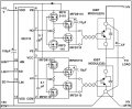
To date, we've designed, built and tested a low power gate driver circuit similar (almost identical) to the one shown in the figure below. The end goal is to use such a circuit to drive a Power MOSFET Module for an electric motorcycle.

Anyways, we built and tested this circuit on a lab bread board that has its own variable 15V and fixed 5V supplies, and everything seems to work fine. However, the final product must have its own low voltage supplied via a DC-DC converter fed by battery bank of the motorcycle which is ~55V.
Thus we need a DC-DC converter capable of supplying us with an isolated 12V(or 15V) and 5V supplies. The 12V(or 15V) supply is used to power the gate driver IC (IR2110) as well as the power buffer circuitry,(i.e. VCC = 12V or 15V) while the 5V supply will act as the logic supply for the chip. (i.e. VDD = 5V)
One simple option would be to find a DC-DC converter that will provide the 55V to 12V(or 15V) needed and simply feed the 12V(or 15V) into a regulator such as the LM7805 and obtain our 5V logic supply from there.
It seems straightforward enough to find a suitable DC-DC converter that will meet our input/output voltage requirements, but I am uncertain as to what our output current requirements are.
According to the application note for our gate driver, the power buffers in the schematic shown above (i.e. the circuitry shown to the right of the IR2110) are needed to provide a higher gate drive current and lower gate drive impedance than what a typical gate driver IC can provide. (Application note is attached below)
They mention that the one shown in the figure above is capable of providing 8A peak output current, which is sufficient for driving Power Modules. (We are using a MOSFET power module, I've attached its data sheet below)
So does this imply that the 12V(or 15V) output from DC-DC Converter (i.e. VCC = 12V or 15V) must be capable of supplying 8A peak output current? The current needed to the drive the gate must be supplied by VCC, right? Or does the power buffer somehow amplify or boost the current?
Thanks for reading!
I'm trying to pick out a suitable DC-DC Converter for our low power gate driver circuitry and I'm unsure about a number of different things.
First some background on the circuitry and what the DC-DC Converter is needed for.
To date, we've designed, built and tested a low power gate driver circuit similar (almost identical) to the one shown in the figure below. The end goal is to use such a circuit to drive a Power MOSFET Module for an electric motorcycle.
Anyways, we built and tested this circuit on a lab bread board that has its own variable 15V and fixed 5V supplies, and everything seems to work fine. However, the final product must have its own low voltage supplied via a DC-DC converter fed by battery bank of the motorcycle which is ~55V.
Thus we need a DC-DC converter capable of supplying us with an isolated 12V(or 15V) and 5V supplies. The 12V(or 15V) supply is used to power the gate driver IC (IR2110) as well as the power buffer circuitry,(i.e. VCC = 12V or 15V) while the 5V supply will act as the logic supply for the chip. (i.e. VDD = 5V)
One simple option would be to find a DC-DC converter that will provide the 55V to 12V(or 15V) needed and simply feed the 12V(or 15V) into a regulator such as the LM7805 and obtain our 5V logic supply from there.
It seems straightforward enough to find a suitable DC-DC converter that will meet our input/output voltage requirements, but I am uncertain as to what our output current requirements are.
According to the application note for our gate driver, the power buffers in the schematic shown above (i.e. the circuitry shown to the right of the IR2110) are needed to provide a higher gate drive current and lower gate drive impedance than what a typical gate driver IC can provide. (Application note is attached below)
They mention that the one shown in the figure above is capable of providing 8A peak output current, which is sufficient for driving Power Modules. (We are using a MOSFET power module, I've attached its data sheet below)
So does this imply that the 12V(or 15V) output from DC-DC Converter (i.e. VCC = 12V or 15V) must be capable of supplying 8A peak output current? The current needed to the drive the gate must be supplied by VCC, right? Or does the power buffer somehow amplify or boost the current?
Thanks for reading!
Attachments
-
 128.4 KB Views: 139
 -
191.2 KB Views: 20
-
274 KB Views: 24
")


