Current Limiting for use with stepper motors

Thread Starter

Mad Professor

Joined Apr 15, 2009
133
Good Day All.

This is my 1st post here so I hope I am posting in the right section.

I have built my own unipolar stepper motor driver board, this works fine, but my design does not have any current limiting so the stepper motors get hot very quick.

The stepper motors I am using are 6.2volts rated at 1amp, I need to run the stepper motors at just over 3 times there voltage (20volts) to have better torque at higher rpm's, but I must not exceed the 1amp limit per stepper motor.

So far for current limiting I have tried using power resistors and even bulbs, this does work, but the stepper motors are not as quick to respond.

The power supply I am using is 20volts @ 7.5amps.
I am running a total of 4 stepper motors plus the driver board from this power supply.

Can someone please be so kind to advice me what will be the best way of limiting the current to each stepper motor.

I know that I could just go out and buy a premade driver board but what’s the fun in that, plus I will not learn.

Thanks for your time.

Best Regards.
 

Thread Starter

Mad Professor

Joined Apr 15, 2009
133
Thanks for your reply.

Here is the datasheet for my Astrosyn MY103H702 Stepper Motors.

Unipolar Configuration
No of Phases: 4.
Resistance per Phase: 6.2 Ohm.
Inductance per Phase: 10 mH.
Rated Current: 1 amp.
Reted Voltage: 6.2 volts.

With the datasheet I am unsure if the shown Rated Current is per phase or total.

I have e-mailed Astrosyn just to make sure.

Here is the Schematic for my stepper motor driver design, (Link) this file is 1783x2486 pixels, 518KB.

Thanks for your time.
 
Last edited:

Thread Starter

Mad Professor

Joined Apr 15, 2009
133
Alberto: Thanks again for your time.

Just looking over your little diag again, you have R1 & R2 = 1.2 / (Motor Current), So I take it thats 1.2 / 1amp = 1.2ohms?

I have just had a quick look on maplin's web site they don't list any 1.2ohm resistors, only 1ohm and 0.22ohm, So I guess I can link a 1.0 & 0.22ohm to make 1.22ohm.

Also does it have to be 5watt resistors as maplin's only have 3,7,& 10watt resistors.

Thanks for your time.

Best Regards.
 

SgtWookie

Joined Jul 17, 2007
22,230
Alberto's solution will work to limit the current, but the regulators will be dissipating a lot of power, and will rapidly overheat and shut down - or just melt. :eek: You'll need big heatsinks on them.

The regulators will have to dissipate (20v-6.2v) x 1a = 13.8v x 1a = 13.8 Watts.

Take a look at the L297/L298 driver/bridge IC pairs, just for ideas. They have an integrated chopper driver, with low-value sensing resistors that measure the current going through the motor. Chopper drivers increase the current through the stepper motor quickly when the phases are stepped, and then limit the maximum current by switching the ground circuit off and on. This keeps the driver much cooler than using a fixed resistance or linear voltage regulator. It's certainly more complicated, though.

They're not going to step as quickly or have the torque that they do right now, as you're operating them at more than 3x their rated voltage. If you really need more torque, you will have to use more capable stepper motors.
 

Thread Starter

Mad Professor

Joined Apr 15, 2009
133
Thanks for your replys.

I will have a look at the integrated chopper driver IC's.

I was aware that the LM317 would put out alot of heat.

Each of the LM317 has it's own HeatSink, aprox 35x13x50mm (9c/watt), Maplin item RN82D, As this is still going to be quite hot I also have cooling fans.

Would you advice adding any Capacitors to this limiter, I already have capacitors to smooth out any spikes on the stepper motor control board.

Thanks for your time.

Best Regards.
 

ygrignon

Joined Jul 30, 2008
2
You may also want to look at the SLA7042M from Sanken. It is a more modern chip than the L297/L298 pair and one chip will do the job. It will also let you do microstepping. I use a PIC 16F84 to control it. It works great and does not waste power.
 

Thread Starter

Mad Professor

Joined Apr 15, 2009
133
Thanks for the info above.

I have been running my stepper motors with the above design at 20volts fine, But I wanted a little bit more speed.

So I have been in contact with Astrosyn they have told me it would be better to run my stepper motors at 36volts.

I now have got my hands on a 36volt 7amp PSU.

With the new PSU in place and the stepper motor static it starts pulling just over 3amps, and slowy drops down to 2.30amps by this point I have to stop testing and pull the power at the stepper motor is to hot to touch.

Can you please tell me how to work out the new resistors values I will need to run my stepper motors at 36volts with a current limit of 1amp.

Thanks for your time.

Best Regards.
 
Last edited:

Thread Starter

Mad Professor

Joined Apr 15, 2009
133
As said in post #11 I contacted Astrosyn the makers of my stepper motors and asked for there advice.

They told me I can run my stepper motors at 36volts but I must not exceed the max amp rated of 1amp.

I am using the Mach3 CNC software, and I am using the ramp up/down settings.

But when running on the 20volt PSU the max travel speed I could use before a stall was 150mm/min, I would like closer to 300mm/min.

Yes I know I am never going to get close to the same sort of speeds as a servo motor.

Yes I know the fast the stepper motor spins the less torque.

Best Regards.
 

AlainB

Joined Apr 12, 2009
39
Hi,

In order to run your motor without a chopper action, you will need to use ballast resistors as you did.

With the 36 volts power supply you would need 2 30 Ohms, 30 watts resistors, one on each of the wire marked as O and M on the unipolar schematic of the datasheet. This is if you want to drive your motors full step and/or half step. For full step you could use only one 15 Ohms, 60 watts resistors on the same wires but joined together. These values are approximative. Take the nearest standard values.

For the 20 volts power supply, the values would be respectively 14 Ohms, 14 watts and 7 Ohms, 28 watts.

The resistors will then take most of the heat and your motor should run just warm. 300-400 RPM is acheivable with a simple driver but not much more.

Here are some small (simple) drivers that I made and they run at a maximum of 360 RPM witch is about 380mm/min. (or 15 inches/min.) when connected to a 24 turns per inch screw:

http://www.youtube.com/watch?v=BAvMMzYG5r4

I would personnaly use the 20 volts power supply unit to drive these motors with ballast resistors.


Alain

Edit: I edited the post to correct an error that I made on the number of resistors to use.

Having had a look at your driver schematic, the driver is not as simple as I was thinking, being loaded with LEDs mostly there in my opinion for the pleasure of the eyes, but I don't see evidence of chopping action. What are IC1, IC2, U2 and diodes D14?
 
Last edited:

Thread Starter

Mad Professor

Joined Apr 15, 2009
133
IC1: HCF4516
IC2: TC4028
U2: LM317
D14: 1N4004

I have been looking around the internet at simple current limters to use with my stepper motors, most of the ones I have found are all based on the LM317 design that was 1st given to me here.

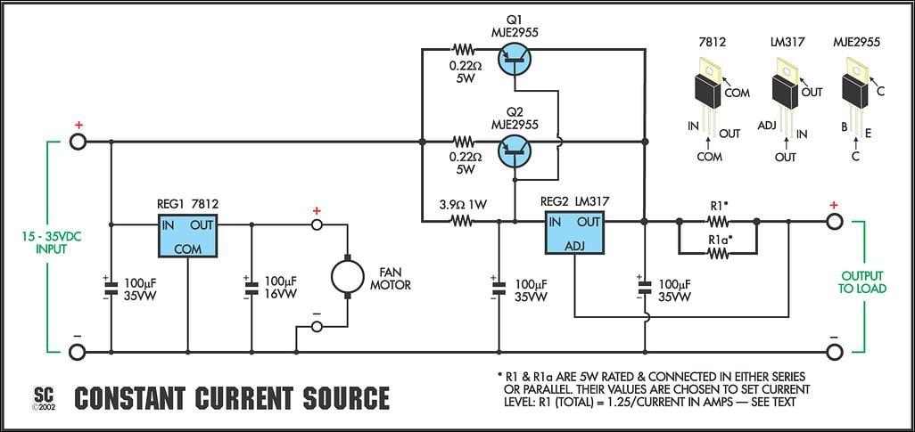
Today I found this design, once again it uses a LM317 but some extra bits.


I am not quite sure what the two MJE2955's are ment to do.

Best Regards.
 

THE_RB

Joined Feb 11, 2008
5,438
They give ability to pass big currents and/or dissipate a lot of heat.

If you are looking at that level of complexity, why not buy yourself a Linistepper kit (or 3) from here;
http://www.piclist.com/tecHREF/io/stepper/linistep/index.htm

It comes with a nice PCB and pre-programmed PIC controller, and will do microsteps with linear smoothing. It's an ideal match for your 6v 1A motors and with the linear microstepping you will find you get much better high speed performance with less input voltage needed.

The down side is it's a kit (but easy to assemble) and like all constant current linear systems it needs a big heatsink.

It does full steps, 1/2 steps, 6th steps and 18th steps.
 

Thread Starter

Mad Professor

Joined Apr 15, 2009
133
I now have a working current limiter on my new power supply.

I found out there was a high voltage version of the LM317.

I ordered a few from RS and it working good again, I can now running at much faster RPM's but I have not fully tested yet.

Thanks for your time.
 
Top