Count Objects with a LDR and a how to connect a calculator (help)

Thread Starter

ofest

Joined Feb 2, 2013
4
Hi guys, thisi s my first post here, and I´m happy I found this site, the circuit I´m trying to make is the following:
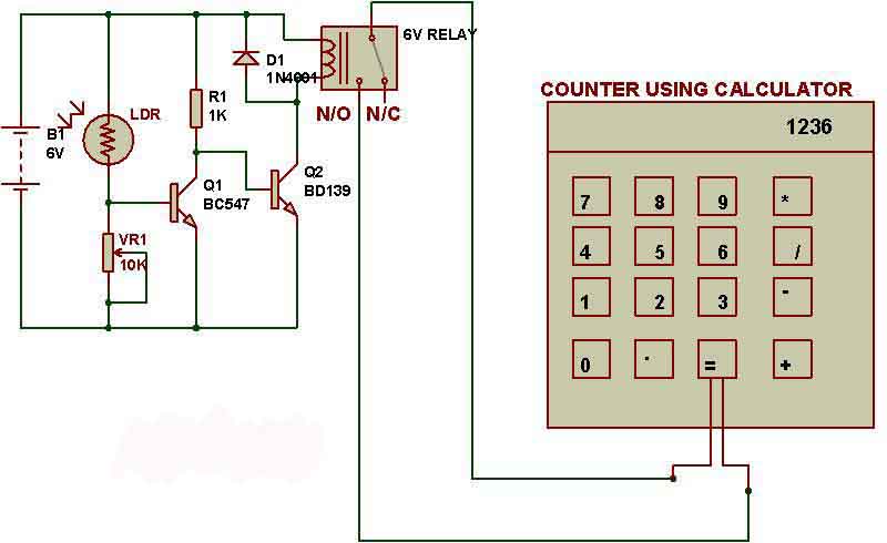


Basically I have to preactivate the calculator so everytime you press the "=" key you get 1+1 and counts evrey object that blocks the light in the LDR.

My doubt is that how do I connect the calculator to the relay, I opened op the calculator and this is what I can see:


The red spot I marked is the "=" key, since I'm new in to electronics I really don´t have a clue how to connect the calculator to the spot I marked, also I would be really thankful if someone could explain me how the transistors are useful in this circuit (I really don´t know) and if what is the purpose of the component "VR1", since I simulated this circuit with a basic software "livewire", and when I increased or decreased it´s value it didn´t change anything.


Also here is the link where I found this project and a video.

Link

http://www.youtube.com/watch?feature=player_embedded&v=YsEGomCY9eQ


Thanks in advance for any help on the matter.
 

Dodgydave

Joined Jun 22, 2012
11,307
Vr1 will alter the level at which the Ldr will conduct and switch on the transistor Q1, depending on the light level.
 

KrisBlueNZ

Joined Oct 17, 2012
111
As Dodgydave said, VR1 changes the brightness threshold at which the circuit will switch. It didn't have any effect in your simulation because you didn't connect it properly in your simulation - the wiper (the arrow on the side) isn't connected to anything, so it behaves like a fixed resistor and its position makes no difference.

To understand how the transistors operate in that circuit, you need a basic understanding of electronic circuits in general, and an understanding of how a transistor behaves. There's a lot of material on this site (separate from these forums) that will help, and material all over the net. Do some learning first, then you can ask specific questions in the forums and people will be happy to help.

That circuit will work, but it only has a single illumination threshold, and when the illumination is close to that threshold, it can witter and activate the calculator button several times, instead of just once. You should use a circuit with hysteresis (http://en.wikipedia.org/wiki/Hysteresis) to get clean switching.

This is how thermostats work - if you turn the control of a mechanical thermostat left and right, and listen for the clicking sound, you will notice that there's a deadband; this stops the thermostat from turning on and off rapidly around the threshold.

In electronics, a circuit with hysteresis is called a Schmitt trigger (http://en.wikipedia.org/wiki/Schmitt_trigger). I've drawn up a simple Schmitt trigger circuit that will do what you want.


That circuit is almost the same as your original design. The difference is the positive feedback created by RE. The two-transistor Schmitt trigger is a well-known design and it's explained on the Wikipedia page I linked to above.

Your calculator keypad uses a rubber mat, with a raised section for each pushbutton. Inside the raised area is an area of conductive coating, which is pushed onto the circuit board when you press the button, and forms a partly conductive path across the interleaved contact fingers on the board.

To simulate pressing the button, you need to connect your relay contact across the contact fingers. You could probably solder some fine wires to them, but you should be able to avoid permanently modifying the calculator, if you use some very thin wires (e.g. wire wrap wire), glued to the board, and just touching onto the exposed areas, or some other part of the trackwork that is electrically connected to them. You might be able to use the rubber mat to press the wires onto the contacts. If you can upload a clearer photo of the keyboard, I may be able to suggest something more definite. You need to tie the wires to a hole in the board otherwise you could easily pull them out.

Finally, I would use a reed relay (http://en.wikipedia.org/wiki/Reed_relay) for this application, and put the relay as close as possible to the calculator. The calculator scans its keyboard matrix with low-voltage alternating signals, and its inputs are sensitive to damage and interference if those signals are brought outside the calculator and run for any distance. The best option would be to mount the reed relay inside the calculator, or at least very close to it, and if you need the calculator to be any distance away from the LDR, the extension wires should be between the circuit and the coil of the reed relay.

My suggested reed relays are:
Coto Technology 9007-05-00: http://www.digikey.com/product-detail/en/9007-05-00/306-1062-ND/301696
9007-05-01: http://www.digikey.com/product-detail/en/9007-05-01/306-1063-ND/301697 (the diode, DC, is included inside the relay)
Hamlin HE3621A0500 http://www.digikey.com/product-detail/en/HE3621A0500/HE206-ND/133255
These are the cheapest compact reed relays available from Digikey with coils rated for 5VDC. The coils all draw only 10 mA current. A BC547 is fine as Q2 (it can switch up to 100 mA).
 

Attachments

Top