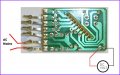
This was from a 60 LED chaser light set, blue and white. There are 16 patterns. I would LOVE to get this to work with a 9volt for say several blue and red LEDs, 10 total maybe. Any thoughts?
Good we can use a 78L05 for the power supply then.
However, there is a large possibility that Q2, Q3 and Q4 on the circuit are SCRs and if this is really the case, then it is NOT possible to use a battery for the controller as a SCR cannot turn off by removing the gate drive.
I should have asked you in previous post about the part number on these but I forgot until I see a 1MΩ resistor taking signal from the rectified but unsmoothed DC supply into the controller.
So what is all the markings on these semiconductor?
Damn. Briefly, can you just expand just a little bit on how hard it might be to make it work on battery? I am open to changing transistors or anything else that it may require.
Damn. Briefly, can you just expand just a little bit on how hard it might be to make it work on battery? I am open to changing transistors or anything else that it may require.
You will need to use a 555 timer and wire it up to generate 100Hz, with the output of voltage high 95%/ low5% duty cycle. This will then be fed to both the controller and the LEDs so they will think it is AC input they are seeing.
As the 555 timer output goes LOW for 5% of the time, the SCRs will turn off when this happens.
This is the idea which I think could work and a 555 is easily obtainable. However there is still some uncertainty in it as no one has tried to do it before.
Would you like to experiment with it, when there is a 10% chance of things don't work out in the end?
Let's put this idea in the public domain for a few days and let others comment on it before actually design a circuit.
A regular 9V battery has too little juice to last only for a few minutes. A 12V gel type battery is more appropriate for your application. What LEDs are you have in mind? Color blue?
I hear what you are saying about the chance of it not working out and agree. Let's see if anyone else has any input on the idea.
Battery size is an issue, so I am not sure 12v is applicable unless there is a small one that powerful available that I don't know about. This is for a 1/18 idea and cant be larger than a 9v, several AA/AAA or other similar size.
That won't do. The TLC555 output can only source 10mA and cannot be used to power a total of 16 LEDs. You can only use a regular 555 like LM555 or NE555 which can source more than 100mA. Otherwise you have to add an extra PNP transistor or P-Ch MOSFET to the TLC555 to boost its output current.
You can have up to three connections(to Q2, Q3 & Q4) for the LEDs and each connection can have multiple LEDs in series per branch and parallel branches. However, owing to the forward voltage drop of the blue LED, you can have at most two in series with a single current limiting resistor in an individual branch when 9V battery is being used. For red LEDs, you can put three in series.
With 16 LEDs, how would you connect these LEDs to each connection?
Here is what I want to put the LEDs in. 4 red where the red is and 4 blue where the blue is, facing outward of course and the same on the reverse (back). If 16 can't work, then whatever equal number that will work and to have in the correct positions..
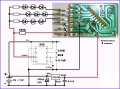
Ok. Here is the circuit diagram and wiring connection.
I only showed a single branch of LEDs per each connection you can use two or more. The limitation is the total output current of the 555 timer, which should be less than 200mA for all he LEDs. The resistor values for the LEDs are not shown but please refers to previous post about the number of different color LEDs you can place in series with the battery voltage you intended to use.
I trust that you know how to take care of the LED connections and calculate the required resistor values yourself.


")