Controlling linear actuator with car alarm and 2 channel relay module WITHOUT an arduino

Thread Starter

Chromecut

Joined Dec 16, 2021
6
Ive connected a 12v linear actuator with built in limit switches to an emylo RF 2 chanel control switch designed for
actuators-It is trggered by a small 3 button keyfob with no manual controls-It works fantastic as it extend/stops/retracts
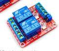
with either one button push in latching mode until stroke complete and can be stopped anytime with 3 button or hold down for continuous stroke and release. to stop-self contained shell-easy wiring attachment included-nice product but I want to trigger it separate from the RF keyfob by way of a car alarm-this emylo model #XL5242MO was purpose made to simply and easily install and control a linear actuator with 5-24V input range-it supplies the actuiatot with power also so pos/neg in and pos/neg out to the motor
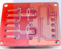
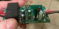
I am trying to determine where on the pcb I can connect the trigger wires from the car alarm to the point where when the RF keyfob button is pressed with the RF receiver processing that signal and then physically triggering the relays
Im not sure what the triggering voltage is (there are no high/low inputs other than 4 lines coming in from the RF receiver daughter card feeding the main pcb with 2 channel relays labeled pos/neg and data
I cooked 2 boards trying to randomly connect the triggers (the car alarm trigger voltage is 12v and the board is rated up to 24v so I didnt think it would short out the board-I even had the keyfob itself being triggered on the button contact points by the car alarm output which then activated the module as if the button was pressed-That proved unreliable so back to the drawing board
no help from the manufacturers for a layout and searching the pcb number gained nothing-Im certain the circuit is easy since the switch is all done only needing 2 trigger wires attached to 2 contact points=project complete
if someone familar with relays could take a peak at the board I have no doubt in a short time those contact points would be discovered quickly
If we need to switch to 2 dpst 12v bosch type relays with one controlling direction and the other feeding power Im fine with that if the circuit diagram is spelled out cut and dry
using a 2 channel relay module with high/low trigger is an option also but meaningless without a diagram

I also have another trigger by way of a kill switch and I believe there is a way to trigger and send in both directions by removing or adding power-basically breaking or completing a junction in the circuit is itself the mechanism that provides the activation
sorry for the winded details but thank you for reading my book

I would be happy to cover lunch for the wizard who can assist

thank you

https://www.amazon.com/dp/B07ZFB9Z9...pY2tSZWRpcmVjdCZkb05vdExvZ0NsaWNrPXRydWU&th=1
 

Attachments

LesJones

Joined Jan 8, 2017
4,190
The signals from the receiver board will not three wires each corresponding to one of the three buttons being pressed. It will be a data stream (Probably one data wire or two wires one data and one clock) Each button will send a different code which will be interpreted on the main board. This will probably be done using a microcontroller chip. Outputs from the microcontroller will then drive the relays.

Les.
 

sghioto

Joined Dec 31, 2017
5,390
Looking at the third photo, Q1 and Q2 are the relay drivers. You can control theses two relays manually by adding this simple extension circuit shown below.
The relays control the direction and operation of the actuator.
Activating via the car alarm may require some additional logic depending on its exact function and assuming there is only a single output from the alarm meaning 0 or 12 volts.
1639851551887.png1639851651470.png

1639851485123.png
 

Thread Starter

Chromecut

Joined Dec 16, 2021
6
The signals from the receiver board will not three wires each corresponding to one of the three buttons being pressed. It will be a data stream (Probably one data wire or two wires one data and one clock) Each button will send a different code which will be interpreted on the main board. This will probably be done using a microcontroller chip. Outputs from the microcontroller will then drive the relays.

Les.
@LesJones yep thats sounds right Im aware it will not accept 3 wires for the 3 buttons as the buttons reverse polarity or cut power-there is no third option which is why there are only 2 data inputs but the point of my post is to change how its controlled from that to how I would like to control it, using a car alarm output and NOT the keyfob-if you look at the picts again zoomed in you will see a small add on board with a coiled antennae wire with four outputs into the main board-zooming in you can see the 2 inner outputs are labeled DATA and remaining 2 outer outputs are labeled pos/neg respectively but where are the microcontroller outputs to connect the car alarm trigger wires to? I believe one relay is used to change direction of the linear actuator (reverse polarity) and the other is to open/close the power flow itself which with the actuator having internal limit switches then the 3 functions are controlled by the three button key fob to either extend or retract and the third button severs power to "stop" the actuator-I would like to install something additonal that controls the power also like a kill switch that is triggered by encountering force against the actuator in case whatever it is moving gets jammed up it will auto shutoff (stop) and reverse direction if thats even possible

any idea on how to use 2 dpst relays to control the actuator?

update*
sghioto
has blessed me by locating the 2 trigger points and has provided a simple diagram to follow
my faith in humanity restored
 

Thread Starter

Chromecut

Joined Dec 16, 2021
6
Looking at the third photo, Q1 and Q2 are the relay drivers. You can control theses two relays manually by adding this simple extension circuit shown below.
The relays control the direction and operation of the actuator.
Activating via the car alarm may require some additional logic depending on its exact function and assuming there is only a single output from the alarm meaning 0 or 12 volts.
View attachment 255464View attachment 255465

View attachment 255462
wow! impressive to say the least-Sir it looks like I owe you a lunch my good man
inbox me your contact info and Ill send out a digital giftcard right away

so Im not sure why the reference to installing a switching diode and a resistor? (Both of which have different voltage choices by the way)(If I was to attempt this brain surgery which voltages?-100ma,200ma 1/2 watt, 1/4 watt, etc) remember I am not using a arduino to control the relays, Im trying to mimic the press of the keyfob button and I would think those contact points you listed have aleady had the proper voltage, tripping frequency/voltage corrected by the on board diodes,resisters and microchips and from those contact points on the "flow" is triggered and maintained by the establsihed relay config already present on the main board-not to mention "I aint as young as I once was" coupled with average soldering skills Im not sure thats possible even I just had to connect 2 wires only to those spots
is it possible to connect those trigger locations to the underside of the board where the 5 points of contacts (total of ten)for each relay? basically let the unit function as it was designed and "high jack" the relays triggering them only with the car alarm output and letting the board deal with power flow,reversing polarity,etc

I believe this can still be achieved with 2 DPST 12v bosch type automotive relays wired together and used as switches instead of relays only where when "tripped" power flows until completion of throw by the actuator with built in limit switches then power is cut then when "tripped again" the polarity is reversed

the car alarms trigger also contains the flashing turning signal lights indicating alarm activation or deactivation but the problem with that is the deactivating trigger is 2 pulses which cancels its self out

I also have a 2 relay module (picture with baby blue colored relays and red pcb) meant for a controller (arduino, etc) but I managed to activate 1 of the two sequences needed by trial an error

there is one remaining option where if by removing or adding power it sets in motion the sequencing of events which is only one event per button push or trigger which Im guessing needs the 2 dpst relays wired in a way that all power is connected to the actuator but disconnected at one place only (the relay trip)and when power is restored at that one point (connection open or closed depending on starting place of actuator) the actuator retracts and then when power is interupted (connection open or closed, again depending on starting place of actuator)the polarity is reversed and the actuator extends or vise versa
so just power on or off can control the actuator
I would be using a simple killswitch to interupt or complete this yet to be determined circuit

any ideas?
 

sghioto

Joined Dec 31, 2017
5,390
Lets see here that's a lot of questions, I'll start here:
Im not sure why the reference to installing a switching diode and a resistor?
That's for "hijacking" the relays as you described and still allows the unit to function as designed.
Here's the schematic of how the contacts are wired on the Emylo.
When both relays are OFF or ON the motor in the actuator is shorted out which acts as a brake.
Activating RL1 or RL2 controls the direction of the actuator.
1639968500740.png
I'm still confused in exactly how the car alarm fits in. So when the alarm is triggered what is it suppose to do or activate and what suppose to happen when the alarm is not triggered?
 
Last edited:

Thread Starter

Chromecut

Joined Dec 16, 2021
6
Lets see here that's a lot of questions, I'll start here:

That's for "hijacking" the relays as you described and still allows the unit to function as designed.
Here's the schematic of how the contacts are wired on the Emylo.
When both relays are OFF or ON the motor in the actuator is shorted out which acts as a brake.
Activating RL1 or RL2 controls the direction of the actuator.
View attachment 255563
I'm still confused in exactly how the car alarm fits in. So when the alarm is triggered what is it suppose to do or activate and what suppose to happen when the alarm is not triggered?
ah I see-that must be how the 2 dpst 12v automobile relay config works but I cannot locate a specific diagram for that config-they always seem to be controlling 2 actuators or a timer is cut into the wiring-or for 6 pin type relay anything other than what I need lol

I am using a PKE (passive keyless entry) feature wherebyes of the car alarm is triggered by a small RF keyfob that when it either enters the area (within 2 meters) or leaves the area it "arms" the system or disarms it-this has presented some challenges also as unitl only recently I wasnt sure what wire did what let alone where to connect them-the fobs trigger the relays which then trigger the actuator which Ive installed on my sliding glass patio door-so my pets can come and go-that was the original intent but Ive come up with a few more uses for a finished product(s) to sell-I have 3 versions Ive been playing with a car alarm, a motorcycle alarm and a motorcycle killswitch-all three have passive keyless ability(basically a proximity sensor picks up the always transmitting keyfobs)the automobile and motorcycle trigger potentials are lock/unlock the doors, (parking light flash once(arm the system)then flash twice (disarm the system)that second flash a problem
and an motorcycle ignition killswitch as the last viable option- this last one is is the easiest setup if I can figure out how by just severing or supplying power which then becomes the mechanism to engage the trigger as there are only 2 wires with the unit between the wires completing the circuit or breaking it (probably with a single relay)
of course that method will need a separate relay wiringsolution with either 2 dpst relays (I think) or the all in one 5v to 36v 2 relay switch modules triggered by low/high I have (ive only been able to wire it for one direction only I just a little help
regarding the emylo unit-thats tight fit to solder plus I have zero knowledge in how to solder and wire the resistors add ons so unless that is our only option (I was hoping to use the backside of the emylo switch to attach my trigger wires where all the relays contacts punch thru the board-but I am grateful for your help in locating the points that are needed but now Im thinking if I take this product to market I will be dependant of emylo and they havent been very helpful
I have the 2 relay module on hand-see attachment but it has too many choices for me to isolate the config I need-so 2 off the shelf relays or the relay module board I have seem like a better course
I imagine the relay board will work exactly like the emylob switch and looking at the back of the main board I can see similarities in layout for the emylo so it should be a piece of cake to distinguish the no2, com2 ,nc2,no1, com1 ,nc1 labeled on the board for someone like you with clear understanding how these things work

The sad thing is I setup a keyless entry door unlock on my camaro over 25 years ago
with the door handles and lock tumbler removed and fiberglassed for theft prevention
I even wired in a manual hidden push button

I wasnt joking about lunch and I will gladly pay you for your time helping me suss this out

Ill cross my fingers that Ive given you what you need and I truly do appreciate the help

thank you
 

Attachments

sghioto

Joined Dec 31, 2017
5,390
What I have drawn up is the Emylo board operating the relay module which will control the actuator.
You actually don't need to solder any connections. I think this is what you are after, the alarm connections will come later.
1640111396992.png
 
Last edited:

Thread Starter

Chromecut

Joined Dec 16, 2021
6
What I have drawn up is the Emylo board operating the relay module which will control the actuator.
You actually don't need to solder any connections. I think this is what you are after, the alarm connections will come later.
View attachment 255734
My good friend I am afraid I have confused you
This is part of a invention business idea and Ive been too tired to spell it out
in digital form, in fact a much more cohesive form which out of respect for you
I owe you that much-In fact I have a proposition you may like (more on that later)

This second option with the 2 relay module is a separate possible from the first emylo option
essentially replacing the emylo-The 2 relay module will be triggered by the PKE activation and the 2 relay module will also handle/route/control power to the linear actuator (I may have to add an additional and separate 12v powerline depicted in your sketch so that did prompt my brain to prep for that)
the 2 relay module is ultimately controlled by the activation and triggering from 2 wires out to "pulse"
the inputs of the 2 relay module using high/low with polarity reversal and power flow directed by the 2 relay module's predetermined wiring config-so it handles the communications AND the powerflow-No need for an arduino or controller-Its a super dumb self contained terminal that ON/OFF is all it does

I own a solar consultation company in Phoenix AZ-I see you are from colorado, I go to colorado springs from time to time-I have several products/enhancements/inventions over various platforms of my personal interests which is of late revenue generation-These are some out of control times we live in and as prepared as I think I am-Its never enough-I want to be financially free while helping those around me
I am usually the resident tech go to but that torch was passed to be extinguished and then neglected
I only just now got fully caught up on win 10 and linux-Now Im playing with persistant ram drives
and doubling PCIE 4.0 speed-I modded my bios to accept NVME drives

I just got a new complete with diagrams PKE (passive keyless entry) unit-It will need trigger input and another 12v 5 pin bosch type relay (It came with one relay pre-wired & pre-configured)
which by the way could be a final choice thus replacing the emylo unit and the 2 relay module

I would also like to compensate you for your time-each one of these changes however aggravating are all still relevant to one idea or the next-you have also helped me to understand as i am pulled in to many directions and if we can monetize it to be self supporting I would humbly hand off the reins to you
picture research and development lab-platinum level power supplies-3 d scanning/printing/modelling
VR-mechanized platforms-Food Generation-Health and wellness-The sky is the limit

please email me at my personal email address.

<Please don't post the Email address on forum, it may bring the Spambot to the forum and your Email, the Email address was deleted>

thank you
 
Top