
Hey guys,
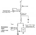
I'm designing a constant current source (on the order of 1A) that needs to be modulated in the hundreds of kilohertz to 1 MHz range. My plan was to have a constant current driver comprised of a mosfet, current sense resistor and an op-amp. There is an inductor in series after the mosfet to keep the current as constant as possible. In order to modulate it, I'm adding another mosfet constant current driver (this one a current sink), in series with the load, to divert current away from the load at high speeds.
The reason I don't want to directly modulate the initial current driver is that this needs to drive loads that are extremely sensitive to surges in current so I'm using the first current driver to set the absolute maximum current, then subtracting from that to modulate the load current.
I've included a diagram. This is my first time posting so I was just wondering if I'm doing anything stupid with this design since I'm relatively new at this (1.5 years out of school, BSEE) and haven't really worked with this kind of stuff.
Thanks a lot
Attachments
-
 57.5 KB Views: 133


