
Hello I am a newbie to electric circuits and I need to build a constant current source to drive continuous current into a chip. Someone told me to use a current mirror to generate this current source, but I have a few questions regarding this. My first question is how a current mirror differs from a norml constant current source with a transistor and LED. I found schematics of this type of constant current source and it seems farily simple. Also, in the schematics of these current mirrors, I am confused where to get the current output from. For example, if I need 50mA current, how do I design this current mirror to generate that, and where in the circuit is the output that I connect to the input of my chip? Can someone please explain this to me? Thank you for all your help.
Constant Current Source, Current Mirror??
- Thread starter robby991
- Start date
Scroll to continue with content
http://zebu.uoregon.edu/~rayfrey/431/notes6.pdf
http://en.wikipedia.org/wiki/Current_source
The two to look at are in the active section.
Then there are these.
http://www.discovercircuits.com/C/constant.htm
http://www.delabs-circuits.com/cirdir/theory/tutors/doc00009.html
http://www.uoguelph.ca/~antoon/gadgets/sccs.htm
This gem will do 10ma, you extend that with a transistor. They show this if you scroll down.
http://poc.purdue.org/docs/caving/LED_Headlamp.pdf
datasheet
http://www.linear.com/pc/downloadDocument.do?navId=H0,C3,P2028,D2715
bloguetronica
- Joined Apr 27, 2007
- 1,541
Never seen a transistor and a LED being used as a current source. Where did you saw that?...My first question is how a current mirror differs from a norml constant current source with a transistor and LED. ...
http://en.wikipedia.org/wiki/Current_source
Scroll down to "Simple transistor current source with LED". The LED replaces the diode. How is a current mirror different/better than this configuration? Both seems to provide a constant current source, I can't seem to figure out why one is preferred over the other.
Thanks for all the information, I am reading up on it now. I'll let you know if I have any questions
A current mirror replicates the input current (with a scale factor), but the direction of the current is reversed. In order to get a constant current out, you need a constant current in.http://en.wikipedia.org/wiki/Current_source
Scroll down to "Simple transistor current source with LED". The LED replaces the diode. How is a current mirror different/better than this configuration? Both seems to provide a constant current source, I can't seem to figure out why one is preferred over the other.
Thanks for all the information, I am reading up on it now. I'll let you know if I have any questions
EDIT: To clarify: In order to get a constant current sink, you have to drive a current mirror with a constant current source. This isn't quite as bad as it sounds, because, while your output current may be subjected to a varying load (current must be constant independent of voltage), the voltage across your input current source generally won't change, except as a function os supply voltage(s) and temperature. In some cases, a resistor is a suitable input current source.
bloguetronica
- Joined Apr 27, 2007
- 1,541
I see! It uses a transistor in its active region stabilized in a common emitter configuration.http://en.wikipedia.org/wiki/Current_source
Scroll down to "Simple transistor current source with LED". The LED replaces the diode. How is a current mirror different/better than this configuration? Both seems to provide a constant current source, I can't seem to figure out why one is preferred over the other.
Thanks for all the information, I am reading up on it now. I'll let you know if I have any questions
Thanks.
A current mirror has the advantage of allowing you to replicate the current that is controlling the mirror n times. You just need to add n - 1 transistors, and all them will have the same current. The disadvantage of a current mirror has to do with temperature. If the transistors are at different temperatures, they will not be able to replicate the driving current correctly.http://en.wikipedia.org/wiki/Current_source
Scroll down to "Simple transistor current source with LED". The LED replaces the diode. How is a current mirror different/better than this configuration? Both seems to provide a constant current source, I can't seem to figure out why one is preferred over the other.
Thanks for all the information, I am reading up on it now. I'll let you know if I have any questions
In fact, the current mirror resembles the circuit of a constant current source without Dz and R2. One transistor is being used as a diode, but with the advantage to have the same characteristics of the emitter diode of the other transistor.
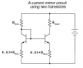
The current mirror implemented with discrete transistors will perform much better if a small-valued resistor (~1% of Rbias in this schematic, also below) is added in series with each emitter. This will minimize the effect of transistor mismatches, and will also raise the output impedance (reduce the change in current as a function of output voltage) of the current mirror.I see! It uses a transistor in its active region stabilized in a common emitter configuration.
Thanks.
A current mirror has the advantage of allowing you to replicate the current that is controlling the mirror n times. You just need to add n - 1 transistors, and all them will have the same current. The disadvantage of a current mirror has to do with temperature. If the transistors are at different temperatures, they will not be able to replicate the driving current correctly.
In fact, the current mirror resembles the circuit of a constant current source without Dz and R2. One transistor is being used as a diode, but with the advantage to have the same characteristics of the emitter diode of the other transistor.
Transistors in integrated circuits can be matched closely, so the balancing resistors are generally not used.
Attachments
-
 9.3 KB Views: 154
One of the easiest constant current sources to assemble is using an LM117/LM317 regulator IC, or it's negative equivalent, the LM137/LM337 and one resistor. It's certainly not the most efficient due to the power dissipation in the resistor.
National Semiconductor has datasheets available on its' site:
http://www.national.com
In the LM117/LM317 datasheet, the current source I'm writing about is described on the bottom of page 18.
National Semiconductor has datasheets available on its' site:
http://www.national.com
In the LM117/LM317 datasheet, the current source I'm writing about is described on the bottom of page 18.
bloguetronica
- Joined Apr 27, 2007
- 1,541
Indeed. That's why a transistor is used instead of a diode (diodes have different V/I curves). I didn't knew about the existence of ICs containing discrete transistors. It would be a good idea to use those, so the temperatures would be more balanced. Can you indicate me some? I'm planning to start a LED flashlight project resorting to current mirrors to control the current (brightness will be more stable).The current mirror implemented with discrete transistors will perform much better if a small-valued resistor (~1% of Rbias in this schematic, also below) is added in series with each emitter. This will minimize the effect of transistor mismatches, and will also raise the output impedance (reduce the change in current as a function of output voltage) of the current mirror.
Transistors in integrated circuits can be matched closely, so the balancing resistors are generally not used.
Wouldn't that require a overhead voltage?One of the easiest constant current sources to assemble is using an LM117/LM317 regulator IC, or it's negative equivalent, the LM137/LM337 and one resistor. It's certainly not the most efficient due to the power dissipation in the resistor.
National Semiconductor has datasheets available on its' site:
http://www.national.com
In the LM117/LM317 datasheet, the current source I'm writing about is described on the bottom of page 18.
I didn't mean to imply that there are integrated circuit current mirrors, I was just referring to current mirrors that occur in various linear ICs (e.g., op amps). The issue with discrete transistors (one per package) is that the emitter area can vary a lot from one to the next. The ratio of emitter currents in a current mirror is linearly proportional to the ratio of emitter areas. Discrete transistors are better than a diode-transistor combo, but adding emitter resistors makes the emitter area mismatch much less of an error component.
There are a number of transistor arrays (e.g. LM3046) that can be used to make current mirrors. I seem to recall seeing a current mirror IC, but I can't find it.
Here is a good resource for current sources and mirrors.
Regarding LM317, all current sources require some headroom, but the LM317 does require 3-3.5V, which is fairly high compared to some less integrated solutions.
bloguetronica
- Joined Apr 27, 2007
- 1,541
Thanks. I was asking about transistor arrays then (I think I called them ICs with discrete transistors, but that name would be much more correct - I just interpreted discrete as separated or independent).I didn't mean to imply that there are integrated circuit current mirrors, I was just referring to current mirrors that occur in various linear ICs (e.g., op amps). The issue with discrete transistors (one per package) is that the emitter area can vary a lot from one to the next. The ratio of emitter currents in a current mirror is linearly proportional to the ratio of emitter areas. Discrete transistors are better than a diode-transistor combo, but adding emitter resistors makes the emitter area mismatch much less of an error component.
There are a number of transistor arrays (e.g. LM3046) that can be used to make current mirrors. I seem to recall seeing a current mirror IC, but I can't find it.
Here is a good resource for current sources and mirrors.
Regarding LM317, all current sources require some headroom, but the LM317 does require 3-3.5V, which is fairly high compared to some less integrated solutions.
I'm aware of current mirrors being used in miscellaneous ICs. For example, the LM1036 has lots of current mirrors.
Thank you everyone for the great info on current mirror. The stuff from the e-book was especially helpful and was easy to understand. From what I understand, there are generally 2 ways generating current sources: from current mirrors, and using voltage regulators (lm 117/317). My question is what is the difference between the two, more specifically, in what situations would you use each? Can you combine current sources and current mirrors? If so, why would you do so? Thanks again!
Hi,
The very old MAT01
And a couple from Zetex:
ZXTD6717E6 and ZDT1053
But I wouldn't go that route for a LED flash light, better use a current feedback switcher.
A few dual transistors:Thanks. I was asking about transistor arrays then (I think I called them ICs with discrete transistors, but that name would be much more correct - I just interpreted discrete as separated or independent).
The very old MAT01
And a couple from Zetex:
ZXTD6717E6 and ZDT1053
But I wouldn't go that route for a LED flash light, better use a current feedback switcher.
You May Also Like
-

Infineon Leverages Coreless Transformer Design in Solid-State Isolators
by Jake Hertz
-

MWC 2024: Three New 5G Devices Boost Networking Performance
by Aaron Carman
-

Nuvoton’s New Microprocessors Target Industrial HMI Applications
by Aaron Carman
-

What’s the Difference Between RS-232 and RS-485?
by Robert Keim