 Facebook
 Google
 GitHub
 Linkedin
First I'd like to introduce myself and thank you for any help that you can offer. All that I know about electronics design is self taught so I very likely have made some stupid mistakes. This is not my first project but it's particularly difficult because I don't know much about analog design. This is not a project for a client.
I need help modifying an in progress design. This device is a receiver in a composite video differential transmission system. The receiver (this design) is implemented with the AD8130 while the transmitter is implemented with the AD8131.
It works beautifully but only with 1000ft of cable. This is because I implemented the reference design without thinking or properly reading...it was a very busy time and I felt like an idiot when I realized what happened.
I need to redesign for variable cable length (gain). While the original circuit was designed for 1 to 100Mhz, I am only really concerned with 1 to 10Mhz being properly compensated.
Here is the existing schematic
View attachment Video-Receiver-v10.pdf
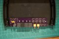
and PCB

This is the reference design
View attachment AD8130_Differential_Video_Receiver.pdf
and the entire datasheet for the AD8130
View attachment AD8129_8130.pdf
I'm not stuck with the AD8130 so feel free to suggest alternate options.
Matt
I need help modifying an in progress design. This device is a receiver in a composite video differential transmission system. The receiver (this design) is implemented with the AD8130 while the transmitter is implemented with the AD8131.
It works beautifully but only with 1000ft of cable. This is because I implemented the reference design without thinking or properly reading...it was a very busy time and I felt like an idiot when I realized what happened.
I need to redesign for variable cable length (gain). While the original circuit was designed for 1 to 100Mhz, I am only really concerned with 1 to 10Mhz being properly compensated.
Here is the existing schematic
View attachment Video-Receiver-v10.pdf
and PCB
This is the reference design
View attachment AD8130_Differential_Video_Receiver.pdf
and the entire datasheet for the AD8130
View attachment AD8129_8130.pdf
I'm not stuck with the AD8130 so feel free to suggest alternate options.
Matt
Attachments
-
 99 KB Views: 124


