
Hi.... m emloying a Class C Amplifier Design for the amplification of an fsk signal
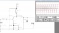
I simulated the whole thing on EWB 5 , worked pretty well, input 30dB, where voltage rms ws 20mV @ 10MHz
and i obtained about 250mV in the simulation.
Now doing this all practically, gave input of 2V rms and results were quite disappointing, my signal rather got attenuated !
I tested the results on 2N3904 BJT !
any suggestions !
I have attached the simulation print screen with results.
Attachments
-
 80.7 KB Views: 69


