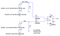
You can do it with 2 sensors and a D flip-flop.
Space the sensors about 29° of cam shaft rotation apart (to allow for FF setup time). I added Schmitt inverters, because the FF is positive edge triggered. The other inverter is not necessary if the Hall effect device has an internal Schmitt, and fast output edges.
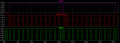
I simulated this for periods (30° of cam rotation) from 1sec to 1usec. Yeah, overkill.
Am I understanding correct that you want to do this without modifying your engine parts? I mean adding extra sensors or machining parts?
If so your forgetting something on how the system works. At least on a spark engine, I'm pretty sure it would be the same on a diesel.
The cam sensor doesn't work by its self, it also uses the crank sensor. While the cam turns through 360° the crank goes through 720°. The "blue" mark on your cam gear lines up with the TDC #1 cyl. space on the crank.(The crank sensor signal comes from a missing tooth on a gear mounted on the crankshaft, usually inside the pan) The two signals only happen together once every two rotations of the crank.
You need to figure out if the sensors give a plus voltage or a "0" voltage as they pass the cam mark and the crank TDC mark.
If it is a "+" voltage both sensor outputs go to a "AND" logic gate. You will get a "+" out put from the logic gate.
If both sensors give a "0", outputs go to a "NOR" logic gate. You will get a "+" output from the gate.
Using the logic gate will give you the out put only when the blue mark is lined up . This is how the the EMC tells when number one cylinder is firing on a spark engine, at least on a GM car.
You can do it with 2 sensors and a D flip-flop.
Space the sensors about 29° of cam shaft rotation apart (to allow for FF setup time). I added Schmitt inverters, because the FF is positive edge triggered. The other inverter is not necessary if the Hall effect device has an internal Schmitt, and fast output edges.
I simulated this for periods (30° of cam rotation) from 1sec to 1usec. Yeah, overkill.
Hey thanks, that is a solution as well, but there is no place to put a extra sensor on the same side of the cam gear. I was hoping to do it without modifying the engine so that it would be a simple retrofit for others.
Am I understanding correct that you want to do this without modifying your engine parts? I mean adding extra sensors or machining parts?
If so your forgetting something on how the system works. At least on a spark engine, I'm pretty sure it would be the same on a diesel.
The cam sensor doesn't work by its self, it also uses the crank sensor. While the cam turns through 360° the crank goes through 720°. The "blue" mark on your cam gear lines up with the TDC #1 cyl. space on the crank.(The crank sensor signal comes from a missing tooth on a gear mounted on the crankshaft, usually inside the pan) The two signals only happen together once every two rotations of the crank.
You need to figure out if the sensors give a plus voltage or a "0" voltage as they pass the cam mark and the crank TDC mark.
If it is a "+" voltage both sensor outputs go to a "AND" logic gate. You will get a "+" out put from the logic gate.
If both sensors give a "0", outputs go to a "NOR" logic gate. You will get a "+" output from the gate.
Using the logic gate will give you the out put only when the blue mark is lined up . This is how the the EMC tells when number one cylinder is firing on a spark engine, at least on a GM car.
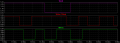
You see, thats what I came to the conclusion on page 2, but when I went out and scoped the signals this is what I get......I take it you didn't catch these?
Red is the crank tone wheel, blue the cam.
The crank blanks always line up with a high signal on the cam.
I feel like I'm missing something very obvious so who ever figures it out be gentle...LOL
Your thread got muddied by all the suggestions as to where you could put new sensors. I understand you want to work with what is coming out of two existing sensors, but I'm still confused as to what you want your new output to look like, and where exactly does it line up with the red and blue traces?
Your thread got muddied by all the suggestions as to where you could put new sensors. I understand you want to work with what is coming out of two existing sensors, but I'm still confused as to what you want your new output to look like, and where exactly does it line up with the red and blue traces?
Oh yes....the ideal would be that I get a cam pulse that would line up with the crank trigger. I initially assumed the blue mark DID line up with the crank trigger, and am left stumped why that isn't the case.
It actually makes sense to me, if you consider that the ECU may be interrupt-driven.
If two interrupts occurred simultaneously, that would make it more difficult for the ECU to determine which item caused the interrupt. However, if the triggers from various sensors are "staggered" events (ie: never occur simultaneously) then it won't have to "decide" between sources. That would make the program code more compact, too.
They may have staggered the events the way they did so that the ECU would have sufficient "warning" to know to look for that 13th trigger. This wouldn't be much of an issue at idle, but if the engine was turning 8 grand, things happen pretty quickly.

 Facebook
 Google
 GitHub
 Linkedin